PatternGenerator
This document describes the installation and features of the ProjectionTools PatternGenerator.
Installation
Use the provided windows installer to install the application on all computers, used for projection (image generators). The Microsoft “.NetFramework 4.0” is required. If it is not already installed on the machine, it should be done now otherwise the PatternGenerator will not start. There is a separate, not officially supported version for Windows XP machines and a separate version with Spout support.
The program can be obtained for various Linux versions. Please contact domeprojection.com for porting to the distribution used.
Operation
The PatternGenerator program is used to display the test patterns during a calibration, alignment and for displaying result data. All projected areas have to be covered by PatternGenerator output for calibration/alignment.
The program menu offers five different starting methods:
- Mulitmonitor:
the software is started on all visible screens. There will be a virtual screen for each device. This is useful if more than one projector is connected to a PC.
- Multimonitor no primary:
the software is started on all visible screens except the primary monitor. There will be a virtual screen for each device. This is useful if using a Laptop (especially with high dpi devices) together with projectors.
- Fullscreen:
the software is started using full-screen mode on the primary device. The resolution is equal to the screen.
- Undecorated:
the software is started as a window with all visible borders removed. The resolution settings are based on the configuration file.
- default:
the software is started with the settings from the configuration file.
After program start the displayed area will appear as blue with some system information printed on screen. This information can be obtained after pressing the ’I’ key on the computers keyboard.

The program offers a few hotkeys:
Key |
Description |
|---|---|
ESC |
kill the PatternGenerator |
H |
Show on screen help |
I |
Show general setup information |
C |
open viewport configuration dialog |
D |
Show viewport layout |
S |
Save current viewport layout |
P |
Save screenshot |
The screenshot is always from the whole Graphic context and can be found
in data/testshot.png.
Configuration
There are different configurations settings and methods, depending on the screen layout.
The PatternGenerator support multiple channels. There will be a virtual viewport inside the PatternGenerator for each projection channel/projector. They are responsible for displaying the content for that given channel. More details about the configuration of the window and the virtual views (aka virtual channels) are below.
Automatic modes
There are two modes that support an automated configuration of the PatternGenerator. Both will span a borderless window across all projectors with a virtual viewport for each channel. No further configuration is needed and already existing virtual viewport settings will be overwritten.
Both modes can be started through the start menu entry or using a command line argument.
- Multimonitor:
The PatternGenerator will start, covering the whole windows desktop. There will be a virtual viewport for each display device attached. This is mode is suited for display computers with more than one projector connected. The command line argument is
-m.- Multimonitor no primary:
This mode behaves the same as Multimonitor but without the primary windows display device. This is useful if a laptop (especially with a high dpi device) has projectors attached or the display computer has not only projectors but a monitor connected as well. The command line argument is
-o.
The information about the setup is extracted from the Microsoft Windows settings, so any changes to this will lead to a different appearance of the PatternGenerator.
The configuration file
The configuration is an XML text-file, which can be edited with any
editor program. It is located at
[Installation Path]\data\config.xml.
The file can be edited through the windows start menu
(PatternGenerator/Edit config) as well.
There are two XML chunks with configuration options for the end user.
The osc port value is the UDP port, where the PatternGenerator
software listens for incoming traffic (commands). This value has to be
entered in all other ProjectionTools communicating with the
PatternGenerator. Change this only if the port is already in use or you
are using more than one instance of the PatternGenerator software on a
single computer.
The following options are available for the osc chunk:
The gfx options are more important. All settings made here are used
by the default starting method of the PatternGenerator (windows start
menu).
Tag |
Default |
Description |
|---|---|---|
loglevel |
2 |
|
width |
|
|
height |
|
|
fullscreen |
1 |
|
undecorated |
0 |
|
hide_cursor |
1 |
|
window_position_x |
0 |
|
window_position_y |
0 |
|
One computer connected to only one projector
If only one projector is connected to the computer, PatternGenerator can be started in full-screen mode via the windows start menu. The default values in the configuration file are using the windows resolution. Other display options can be set, as described previously.
One computer connected to multiple projectors
There are setups where more than one projector is connected to a computer. In that case certain specifications on the computer and PatternGenerator have to be made.
First step is to set up the display alignment on the computer. For later reference it is the easiest way to put the displays all next to each other (vertical, horizontal or as a grid).
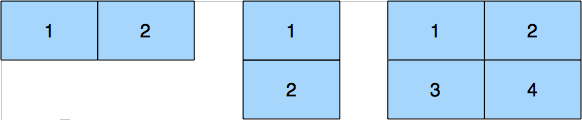
If the layout is a regular grid of screens with the same resolution and the PatternGenerator can open a window/screen spanning all visible projectors, an internal configuration dialogue can be used. Open it with the ’c’ key.

Enter the number of columns and rows and the resolution of one display. Press save to store the values permanently. Cancel aborts and pressing the ’c’ key again applies the changes but doesn’t stores the data in the configuration file.
In order to check the settings ”d” can be pressed to display the viewport layout. Each physical projector image should show a white border with size and channel information to visualize the displays.
Note that all of this settings are independent from the previously described graphics settings, which are global.
Manually editing the Virtual Display configuration
In certain cases more detailed control of the Virtual Displays is
needed. If different resolutions or positions are used for instance. The
data/viewports.xml file can be edited to match those cases.
First make sure that the simple attribute of the viewports tag is set to ”0” instead of ”1” (1 enables the settings of the simple configuration dialog) which is on top of the file.
<viewports simple="1">
Then you can add as many viewport chunks as needed to the file. Refer to the following table for details:
Tag |
Description |
|---|---|
channel |
The channel used for communication with the viewport. They should start with 0 and are incremented with each channel. |
left |
Left position of the virtual viewport inside the PatternGenerator window/screen |
right |
Right position of the virtual viewport inside the PatternGenerator window/screen |
top |
Top position of the virtual viewport inside the PatternGenerator window/screen |
bottom |
Bottom position of the virtual viewport inside the PatternGenerator window/screen |
Example
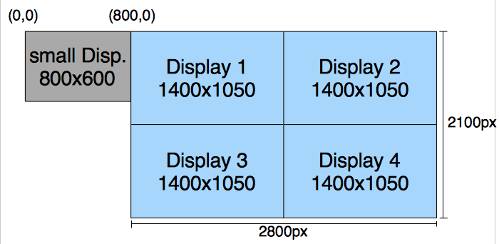
The next figure shows a more complex setup, which has to be configured by editing the appropriate files. For more details to all following settings refer to chapter ”The configuration file”. This example has 4 projectors with a resolution of 1400x1050 that are set up as a grid and one additional display that will not be part of the projection.
First the program screen/window output has to be set up. Edit the config.xml file in the data folder so that the gfx chunk looks like this:
<?xml version='1.0' encoding='UTF-8'?>
<application version="4.0">
   <loglevel>2</loglevel>
   <osc><port>11000</port></osc>
   <tcp><port>11001</port></tcp>
   <udp><port>11002</port></udp>
   <gfx>
      <width>2800</width>
      <height>2100</height>
      <fullscreen>0</fullscreen>
      <undecorated>1</undecorated>
      <hide_cursor>1</hide_cursor>
      <window_position_x>800</window_position_x>
      <window_position_y>0</window_position_y>
   </gfx>
</application>
Since you can’t possible create a windows fullscreen window, covering the desired output area we have to use the undecorated window mode, which leads to the same optical result. The main advantage of this mode is, that we can span any desired area of the outputs and move this window to any position.
Within the \(<\)gfx\(>\) tag the \(<\)width\(>\) and \(<\)height\(>\) defines the full resolution of the setup that is used for the calculation of the screen distortion, in this case the displays marked blue. For those four displays the full resolution is 2800x2100. Since the PatternGenerator should only be seen on the specified displays \(<\)fullscreen\(>\) will be set to 0. Also important is to set the mode to undecorated, and to hide the mouse cursor (set value here to 1) to avoid window borders or the mouse cursor creating wrongly recognized dots later on. The window position has to be set to the value where the top left corner of your group of displays is within the windows arrangement. In case of the example the window position for the PatternGenerator is 800 for x and 0 for y.
To define the displays within the PatternGenerator viewports need to be assigned to each display. First make sure \(<\)viewports simple=”0”\(>\) is set to activate the manual settings.
Then add a viewport chunk for each projector, entering the appropriate channel number and the display positions as in the following example:
<?xml version='1.0' encoding='UTF-8'?>
<display_channels version="4.0">
   <viewports simple="1">
      <num_h>1</num_h>
      <num_v>1</num_v>
      <h_size></h_size>
      <v_size></v_size>
      <viewport>
         <channel>0</channel>
         <left>0</left>
         <right>1400</right>
         <top>0</top>
         <bottom>1050</bottom>
      </viewport>
      <viewport>
         <channel>1</channel>
         <left>1400</left>
         <right>2800</right>
         <top>0</top>
         <bottom>1050</bottom>
      </viewport>
      <viewport>
         <channel>2</channel>
         <left>0</left>
         <right>1400</right>
         <top>1050</top>
         <bottom>2100</bottom>
      </viewport>
      <viewport>
         <channel>3</channel>
         <left>1400</left>
         <right>2800</right>
         <top>1050</top>
         <bottom>2100</bottom>
      </viewport>
   </viewports>
</display_channels>