About Align
After a projection system is calibrated once, it usually does not stay perfect over its whole lifetime. A thermal drift, drift induced by a motion platform, a loose optic, a lamp exchange or a projector exchange might noticeably change the resulting projection. To get a perfect image again the system would need a new calibration. Doing normal calibrations all the time might be too time consuming, especially when the screen shape is not perfect and needs to be captured stereoscopic using multiple camera positions, or a big mockup stands in the projection system after initial calibration which might be difficult or impossible to remove for recalibrations.
Assuming the screen shape is not changing and some permanent, stable reference points are available, recalibrations usually can be automized, and by reusing data from an initial calibration requiring less camera positions than during initial calibration.
Align allows to re-align drifts in already calibrated, fixed installed projection systems, using digital cameras and a high degree of automation (support for multiple fixed installed cameras or a camera on rotation unit). Align generates new data that is the basis for Mapper2d/Mapper3d to calculate updated warping and blending information.
Align keeps the initial calibration data (created with Creator) untouched so that the Mapper2D/3D could always switch back to the initial calibration data. It makes also use of the initial calibration data to extrapolate uncaptured areas on the projection surface, which might be obstructed by a mockup during recalibration.
In normal operation mode Align has an interface focused on running recalibration, hiding options only needed during setup. This makes the user interface more clean and avoids breaking an alignment configuration by accident.
Align needs to capture test-patterns on the projectors. For that purpose it needs:
A testpattern generation program running on display computers attached to the projectors (PatternGenerator
network connection to display computers to communicate with the testpattern generation program
a calibrated camera attached to the computer, where Align is running on
The following chapters describe the UI components of Align and the basic workflow of doing re-alignements.
Startup Parameters
Align can be started with a project file as parameter. And the automiation pipeline can be run automatically.
There is also a commandline version of Align, called AlignC, intended for batch scripting. Both executables support the same options and arguments.
Align [options] project
AlignC [options] project
- Options:
Option
Description
-?, -h, –help
Displays help on commandline options.
-v, –version
Displays version information.
-r, –run
Run automization pipeline on startup.
-s, –simulation
Run in simulation mode
-u, –noui
Don’t start with user interface.
- Arguments:
Argument
Description
project
Path to projects configuration xml that should be loaded on startup.
Creating an Align Project
An align project is meant to be used for recalibrating a fixed installed system multiple times in an easy and fail-save as possible way.
The Align program shows a reduced GUI focusing on recalibrating the system with a few clicks.
The align tries to use as less as possible cameras/positions by basing the recalibration on an initial calibration, that had captured the screen geometry and initial projection placement. Thus, an align project is tied to a distinct site/projection-system and should not be copied between multiple sites.
Align keeps the initial calibration data (created with Creator) untouched so that the Mapper2D/3D could always switch back to the initial calibration data.
Conversion using new camera positions
The align project is created from a normal creator project by exchanging cameras and defining new camera positions using the following steps:
Do a normal calibration of a system using Creator, and verify the results.
Open Align program
Activate service mode using
Help/Service Mode...Generate an align project for your initial creator calibration using and follow the wizzard, that allows to select the original project and a new set of cameras. The modified project is automatically opened in align.
Setup camera positions for the new camera set, like it is done in the normal creator.
When everything is setup and automated, the alignment can be run through by just hitting the play button in the toolbar.
After leaving the service mode the position configuration can no more be changed.
Reusing initial camera positions
Sometimes the initial calibration with creator might have been done using fixed installed cameras, that will be used for Align as well. In that case the Creator project including its used cameras and positions can be transferred to an Align-project directly from Creators file menu.
Load the project in Creator
use
File/Transfer Creator Project to AlignSave and close project
Open project in Align
Running an Align Project
The following chapter describes an autoalignment process and discusses possible issues.
General preparations
Clean up the space in the projection area. Remove all obstacles in front of the projectors, laser markers and cameras. Remove cover from camera optics.
Turn off all lights and make sure, that nobody enters the area during picture taking.
Turn on the control pc, the visualization computers, the projectors and the cameras.
Leave the projectors running for at least 30 minutes.
Switch all eventually existing warping-hardware and warping-software into bypass mode. The image from the visualization computers must be shown native, without geometry correction or blending applied.
Start the PatternGenerator software on all Igs (Program menu or
c:\domeprojection\PatternGenerator\PatternGenerator.exe). All Channels will display a domeprojection logo.
Starting the process
There are two ways to do the alignment, depending on the integration. The process is either full automated or semi-automatic. Both variants are described below.
Full Automated Alignment
This type of calibration is typically used, for systems with multiple fixed installed cameras or with one camera on a motorized mount.
Start the Align program on the control pc. The corresponding project should automatically be loaded. If it is not loaded, use
File/Load Project....Check connection to visualization computers and if there is still any warpunit or warpsoftware active: Select all projectors (click into projector list and press
CTRL-a) and press the black/white preview buttons to test the connection. You have to check if the blending is still visible in the white preview.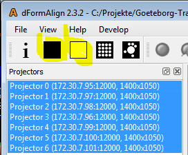
Connect to the cameras using the camera button. You have to see a live preview of one camera. If not, check the connection with the camera driver software, and try to connect again.

Start alignment with the run pipeline button. A progress bar appears and patterns are displayed on the projection. When the process is finished a message window will appear.

Save the project and open it in Mapper2D/3D for checking results and exporting data.
Semi automatic Alignment
This type of calibration is typically used, when only one camera without motorized tripod head is available, but multiple camera positions/orientations are needed to capture the whole projection system.
Start the Align program on the control pc. The corresponding project should automatically be loaded. If it is not loaded, use
File/Load Project....Check connection to visualization computers and if there is still any warpunit or warpsoftware active: Select all projectors (click into projector list and press
CTRL-a) and press the black/white preview buttons to test the connection. You have to check if the blending is still visible in the white preview.
Connect to the cameras using the camera button. You have to see a live preview of one camera. If not, check the connection with the camera driver software, and try to connect again.

Move the camera to the position that should be captured. The camera positions are typically predefined on site. There are either, multiple mounts where the camera can be attached or a tripod needs to be rotated to defined angles.
Check and calculate the camera position of a position, that should be captured. Double click on the camera column of corresponding position.
The Find Position window will open up.
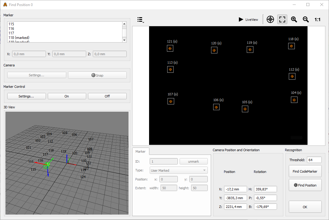
Turn on the position markers (lasers) with the Marker Control On button.

- Then take a picture with the Snap button so you can see the laser markers and the expected positions.If the white dots (laser markers) are inside the blue rectangles the camera position is good. The camera position is bad if they are outside or on the blue lines.
Fix bad camera positioning (markers outside blue rectangles) by doing one or both of the following:
If the camera positioning/orientation is completely done by hand, check positioning of the tripod, and try to adjust the tripod head (typically a gear head with seperate precise controlls for heading, pitch bank)
If the camera is attached to fixed mounts or the camera orientation can not controlled so detailed, that all markers lie in the blue rectangles, move the white rectangles, so they fit the markers.
To do so, just drag the rectangle with the mouse in the camera image to match the expected position.
If all markers where correct or you have moved all markers to the new position, press Find Position.
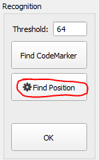
This will take new images and calculate the camera position. If the settings where correct you’ll get orange circles with a cross inside for all markers.

If you get this result, close the pos finder window with ok. If not, redo from step 5.
Select the position with the mouse (click on pos. or Camera column).
Note
It should become highlighted as well as the projectors in the projector dock. If not, click on another position and then on the position you want to measure.
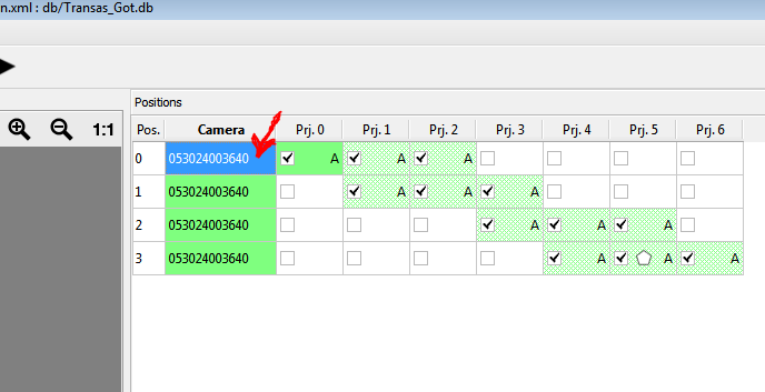
Start alignment for this position with Take Images and Analyze button. A progress bar appears and patterns are displayed on the projection.

If all selected projectors for a position are marked green (as in the image from step 12). The capturing of the current position is finished.
Repeat steps 4 – 14 until all positions in the project are captured.
Calculate the alignment results with Generate 3D button. The autocalibration run is now finished.
Save the project and open it in Mapper2D/3D for checking results and exporting data.
Troubleshooting
Dotpattern detection
There are several potential reasons for dotpatterns not correctly or only partly detected.
Some common reasons are:
Warping or blending inside projectors or warp units is still switched on during calibration. This results in dots partly invisible due to blending and dots projected on different places, due to activated warping. Solution: Turn off warping and blending, then do a new calibration run.
Temporary objects or light in the room during calibration (flash-lights, room lights, people or others). Solution: remove these objects or lights and repeat the calibration run.
Brightness of projectors has changed, resulting in much darker or brighter images taken. Solution: adjust recognition parameters or camera shutter speed and repeat the calibration run.
Network communication problems may result in many points (usually rectangular blocks) are missing. Check your network setup, stop potentially interfering software and repeat the calibration run.
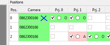
The positions table in Align gives a quick overview of the measurement results, and where potential problems have occurred. The quality of the measurements is visualized as colors in the positions table (green, yellow, red). Individual colors are shown in the position table for each measured projector on each camera position.
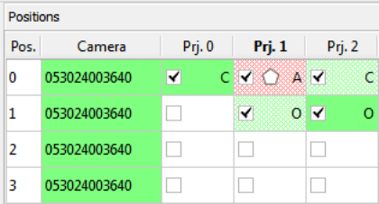
- green:
the same amount of dots where detected as where projected.
- yellow:
a few dots less than projected where detected
- red:
many points where not detected or more points where detected than projected
This color coding is based only on comparing the number of detected and the number of projected dots. There is still a chance, that some points where detected at the wrong place if a cell is colored green (same amount of points detected as projected). This can usually happen if reflective materials or projector lenses are visible to the camera.
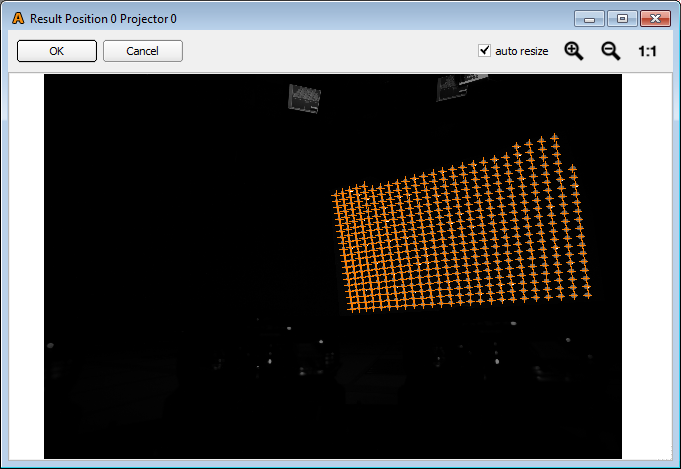
More detailed information can be shown by double-clicking on one of these table cells. An additional window opens showing the captured camera images and the recognition results.
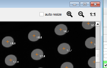
All orange crosses (these mark recognized points) must be placed in the center of the gray circles.
All circles should have an orange cross inside.
The pattern should
A detailed view (use the magnifying tools) looks like:
External objects (lights, people in the room or else) which disturbed the process should be visible here. Remove those objects and repeat the alignment process.
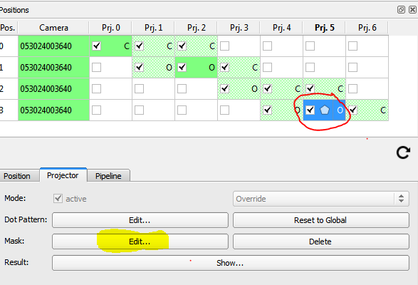
If there are permanent obstacles or disturbing lights in the picture these should be removed with a custom mask. Usually such objects are already masked out during the setup of an align project. Projector 5 in position 3 is an example, where such a mask is applied. To show this editor, select the projector and press the Mask: edit button.
This will pop up the following window:
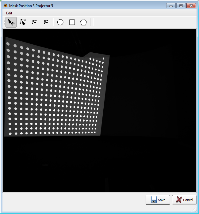
Here the area which is considered for the image processing can be adjusted. For details on using the Mask Editor, refer to chapter Mask Editor.
Camera position detection
If the camera position cannot be detected, this is shown in the camera column of the positions table. The table cell of corresponding position is transparent, indicating that the camera position was not found.
The Find Position dialog reveals details of the position finding process. This dialog can be opened either by double clicking on the corresponding cell in the positions table or by selecting the corresponding cell and then clicking the “Find Position…” button in the Position tab below the table.

In the visible camera image check if the reference markers are in their corresponding region of interest.
If the markers are all far off their region of interest, the camera probably has moved significantly, and should be moved back. In order to do so, turn on the markers and the live view. Than move/rotate the camera, until the markers are in the corresponding region of interest again, or at least very close.
If the region of interest, are just a bit off, the camera has rotated only slightly. In that case the region of interest can be moved over the corresponding marker again, by drag and drop.
If the camera has moved/rotated you should also check if the dotpatterns shown for that position, still all fit into the camera image. If they don’t fit anymore, either the camera position/orientation should be adjusted, or shown dotpatterns must be adjusted.
Mainwindow Overview
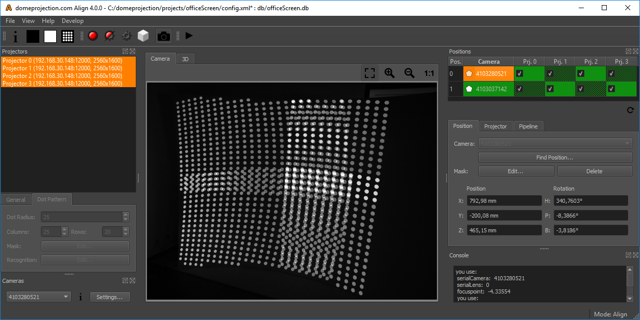
Align has a fully configurable workspace. Figure 1 <#fig:Align shows the default configuration with the typical widgets open.
- Menus
- File Menu
Load and save projects (Additional options available in Service mode).
- Tools Menu
Additional tools and advanced operations on loaded project. (only available in Service mode)
- View Menu
Workspace and theme management.
- Help Menu
Help, Support and Program information.
- Toolbar
The toolbar provides quick access to several preview and capture actions. For details see sections Previews Toolbar, Capture Toolbar and Pipeline Toolbar.
- Hardware
On the left are docks for all the components involved in the project listed.
- Projectors
The projectors dock widget shows a list of all projectors in the current project and allows to edit projector related settings.
- Cameras
Each project has at least one camera. In the cameras dock widget the cameras of a project can be viewed and their settings adjusted.
- Camera View/3D View
In the center of the window is a camera-view and 3d-view available between which the user can switch.
- Positions
On the right side is the configuration of the calibration process visible.
All dock widgets can be arranged, stacked, opened and closed by user. The workspace layout is saved persistently.
It is also possible to revert to the default workspace using View/Default Workspace.
All available dock widgets can be found in the menu. They are described in the following sections.
The theme can be switched in View/Theme. An application restart is needed for a
theme switch to take effect.
For using the maximum workspace on the desktop, a full screen mode can
be enabled in View/Toggle Fullscreen Mode.
Previews Toolbar

Preview Toolbar
- Identify
show info on selected projectors
- Projector dark
make selected projectors black
- Projector light
make selected projectors white, others black
- Project Dot Pattern
show dot pattern on selected projectors
Capture Toolbar

Capture Toolbar
- Take Images
Take test-image sequences with selected camera for selected projectors, without further image analysis. During capturing process, neither cameras nor projectors should be moved.
- Take Images and Analyze
Take test-image sequences with selected camera for selected projectors, and analyze images. During capturing process, neither cameras nor projectors should be moved.
- Analyze Images
Analyze images for selected position and projectors. This can be used to analyze previously taken images again after change of recognition parameters or masks. It is much faster than taking images again, and no attached cameras are required.
- Calculate Align
Reconstruct projection geometry by analyzing all images taken for projectors, camera positions and screen geometry information.
- Toggle Camera Connection
Enable/Disable camera connection. New images can only be taken, if camera connection is active
Pipeline Toolbar

Pipeline Toolbar
- Run Pipeline
Starts the full realignment process. Take and process images for all camera positions and projectors.
Camera View
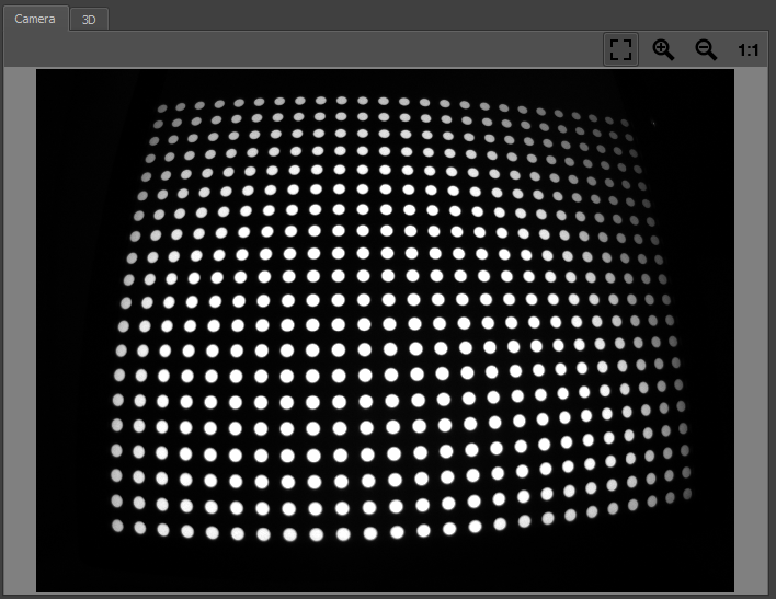
The camera view shows a live stream from currently active camera.
If the camera is turned off, switch it on using (see section Capture Toolbar).
Camera View
- Navigation
The view can be dragged with the left mouse button.
- Scaling
The camera image is typically fit into the window. Additional scaling options are available at the top right corner of Camera View.
3D View
3D View
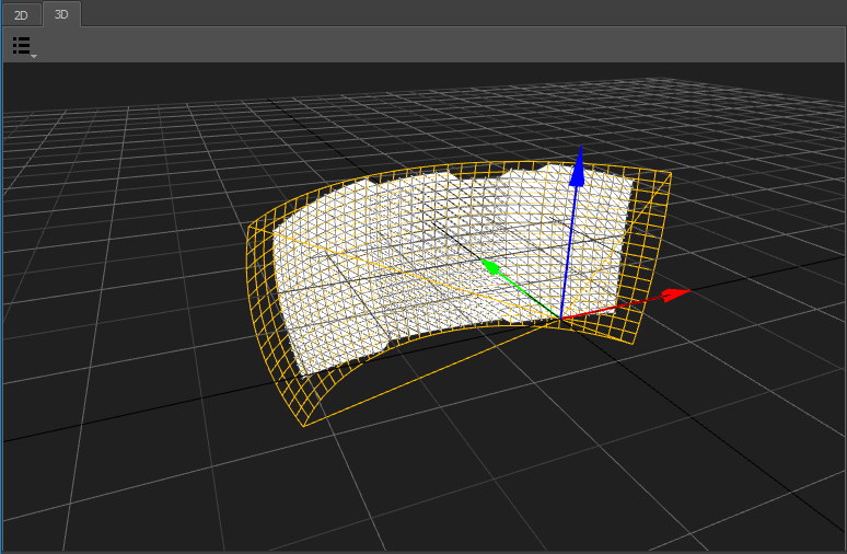
Visualization of currently selected Screen-type, reference points, measured geometry from selected projectors and position/orientation of selected camera position.
Several aspects of the visualization can be toggled in this views toolbar at the top edge.
- Visualization Options
A drop down menu on the top left corner allows to select multiple visualization options.
- Screen
Theoretical/imported screen shape
- Reference Points
Imported/generated reference points
- Geometry:
Generated 3d shape of initial calibration
- Measured Points
Measured 3d positions of initially captured points for each projector.
- Align Points
Measured 3d positions of captured points after recalibration for each projector.
- Perspective
Switch to predefined orthographic views or the default perspective camera position.
- Navigation
Navigate the 3d view using the mouse.
- Rotate
Left mouse-button- Move
Middle mouse-button,Alt+Shift+LMB- Zoom
Right mouse-button,Alt+Ctrl+LMB
Projectors
Projectors reflect one projection channel each. Usually one channel is used per projector. In some setups with 4k projectors, there might be more channels in the project than actual projectors.
The projectors dock widget shows a list of all projectors in the current project and allows to edit projector related settings.
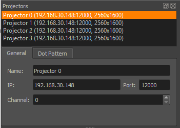
Projectors
List
A list shows all projectors in the project. Including name, ip, port and resolution.
This widget allows multi-selection of projectors.
Several other views in the application update according to the current projector selection.
If a single projector is selected, its related settings can be edited in the editor below.

Projectors list
Press Ctrl+A to select all projectors at once or hold Ctrl or
Shift to add projectors to current selection.
General
Adjustable in service mode only (see section Service Mode)
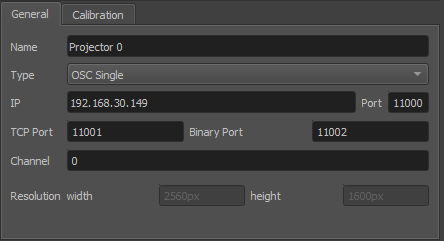
General projector settings
- Name
Arbitrary string describing the projector
- Type
Interface to use for showing testpatterns.
- OSC Single
Default PatternGenerator based interface. Works with up to date PatternGenerator.
- OSC Multi
ProjectionTools channels are virtually split into multiple PatternGenerator channels. Works with standard PatternGenerator.
- OSC Legacy
Can be used for very old PatternGenerator installations, or installations on limited/embedded hardware. The preview functionality is limited.
- NDI
Provide testpatterns as one NDI-stream per channel. This can be used, if it is not possible to install PatternGenerator on the Mediaservers. Several Mediaservers support recieving and showing NDI-Streams. The preview functionality is limited.
- Norxe Unify
Send testpatterns as image directly to Norxe Unify projectors. This allows calibration without access to IGs.The preview functionality is limited, and not interactive.
- Barco Pulse
Send testpatterns as image directly to Barco Pulse projectors. This allows calibration without access to IGs.The preview functionality is limited, and not interactive.
- Luna
Send testpatterns as image directly to domeprojection Luna warp units. This allows calibration without access to IGs.The preview functionality is limited, and not interactive.
- Warper4k
Send testpatterns as image directly to Westar Warper4k warp units. This allows calibration without access to IGs.The preview functionality is limited, and not interactive.
- IP
network address of computer where PatternGenerator software is running on
- Port
port to communicate with PatternGenerator. By default 12000. If multiple PatternGenerator run on one computer different ports need to be used.
- Channel
channel number, only used for PatternGenerator virtual where one PatternGenerator: instance shows patterns for multiple projectors
- Width and height
Have to be the same as the physical projector resolution used in the projection and displayed here for reference only (not editable).
Dot Pattern Settings
During the alignment process a special test-pattern is shown on each projector, and captured by cameras.
The basic settings of the dot pattern (Dot radius, columns and rows) are not editable in Align. These settings were already defined during the autoalignment setup.
There is still the possibility to deactivate distinct dots of the pattern in a separate editor.
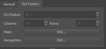
Dot Pattern
- Dot Radius
Radius of projected dots in pixels. Might need to be changed depending on how big the points are seen in the camera image.
- Columns/Rows
Number of dot columns and rows.
- Mask Edit
Allows to edit the Dot Pattern (see DotPattern Editor section Dot Pattern Editor).
- Recognition Edit
Allows to edit and test recognition parameters in an editor with visual feedback (see section Recognition Settings).
Recognition Settings
The test-patterns captured by cameras need to be analyzed. This recognition process consists of several steps:
Capture multiple images:
Black-image (points off)
all dots image
multiple images with just part of the dots projected (this step is left out during recognition parameters setup and testing)
Calculate difference image between points image (points projected) and black-image (no points projected)
Generate binary (black/white) image using a defined binarisation threshold (pixels darker than the threshold become black, brighter pixels become white
Detect outlines of white image areas
Remove white areas in the image that are too big or too small and are probably not dots.
Detect point centers from outlines
Detect point id by analyzing sequence of dot pattern images (this step is left out during recognition parameters setup and testing)
The recognition settings editor allows to edit and test recognition parameters with visual feedback.
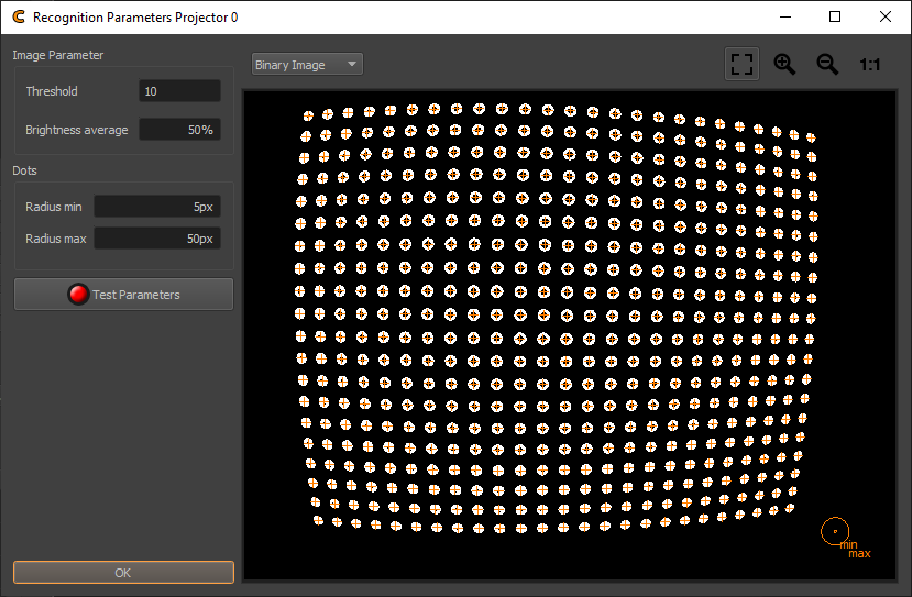
Recognition Parameters Projector
- Threshold
The binarisation threshold controls the generation of the binary image from the difference image of black-image and points image. Pixels darker than the threshold become black, brighter pixels become white. This value should be setup in a way so that each point is clearly visible as a seperate white dot in the “Binary Image”. If the value is too small points might start to merge into one big white area. If the value is too high, points start to vanish.
- Radius min/max
The minimum and maximum radius of circles in camera image in pixels. Only circles within this range are detected. The camera image contains an overlay in the bottom right corner, visualizing the current radius min/max setting.
- Test Parameters
Take images with camera, analyze and show results. The Editor allows to show several images from the recognition process:
- Black Image
First image taken with camera. Should contain no dots.
- White Image
Second image taken with camera. Should contain dots.
- Average Image
Average of Black and White Image
- Binary Image
Black/White Image. Dots should be full white, rest should be black, otherwise check threshold and camera parameters.
- Contour Image
Shows contours around each dot. Each dot should have exactly one closed contour.
Orange crosses are drawn on every detected point center.
Cameras
Each project has at least one camera. In the cameras dock widget the cameras of a project can be viewed and their settings adjusted.

Cameras dock
- Combobox
Shows currently selected Camera.
- i
Shows general information about camera type and lens.
- Settings
Allows to adjust camera parameters in a separate Editor.
Camera Settings
The Camera Settings dialog allows to adjust camera settings, mainly to adjust the brightness of captured images.
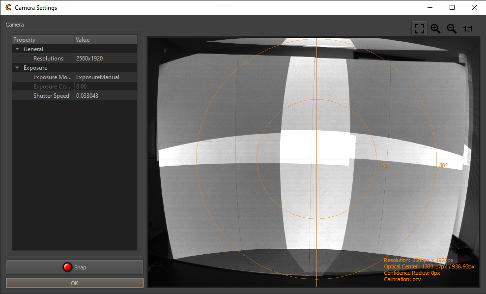
Camera Settings
The editable camera parameters are depending on the camera type. Some typical parameters are:
- Camera shutter
The time the shutter is open to take one image. Higher values result in brighter images
- Camera gain/iso
Gain of camera signal, high values result in grainy images. Low values preferred.
- Camera aperture
adjust the lens opening. Higher values reduce the lens opening and result in darker images.
- Start Automatic Parametrisation
Analyses the camera image brightness and sets an appropriate shutter, gain and iso. This is an iterative process continuously updating the values while activated. Press the button again to stop analysis and keep the current settings.
- Snap
Capture a new camera image using current settings.
- Visualization
An overlay on the camera image visualizes the field of view and the principal point. Additional informations about camera resolution and calibration are show on the bottom right corner.
The camera parameters should be set such that the projection is clearly visible but not too bright.
Positions
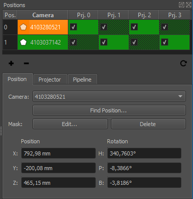
Positions Editor
The realignment process typically involves image capturing from multiple positions. There might be individual cameras at each position or there is just one camera that is moved/rotated around to all the predefined positions.
The positions editor gives an overview of all these positions, which camera is used for each position, which projectors are captured from each position, how capturing data from multiple positions should be merged, calibration result and several more.
The positions editor also allows do adjust camera position related parameters.
Positions Table
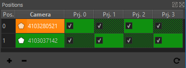
Positions Table
- Cell Color
Quality estimate of measurement result based on comparing the number of detected and the number of projected dots.
- Green
The same amount of dots where detected as where projected.
- Yellow-Red
When less than 100% of the projected points where detected, the color gradually changes from yellow (99% detected) over orange to red (0% detected).
- Red
No points, or more than projected points where detected.
- Cell Fillpattern
Dithered if dot pattern where overridden, solid otherwise.
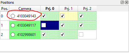
- Polygon Icon
Shown if a mask is defined.
- Checkmark
A cell is checked, if a projector is activated for calibration on a distinct position.
- Update Position List
refresh positions table
- Doubleclick Camera or Position
open PosFinder for camera position
- Doubleclick Projector
Open calibration result for projector. (see section Result View)
- Context Menu
Quick access to camera/projector related editors.
- Add Position
add new position with currently selected camera and projectors. (service mode only)
- Remove Position
user defines exact position of marker/feature in image. No image analysis is done for this marker. (service mode only)
- Update Position List
refresh positions table
Position Tab
- Camera
Select the camera that should be used on this position. (service mode)
- Mask Edit
Edit a mask that is applied to the camera image to avoid false point recognitions, e.g. reflective surfaces or flashing projector lenses. It can be combined with projector masks. (see section Mask Editor)
- Mask Delete
Delete mask and use complete camera image for detection.
- Find Position
Find camera position and orientation using Position Finder (see chapter Position Finder).
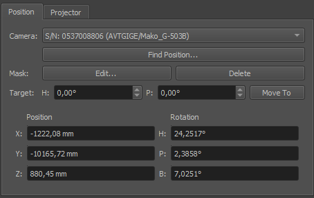
- Position/Rotation
Camera Position and Orientation on this position.
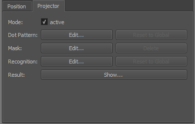
Projector Tab
- Active
Set if selected projector on selected position should be active for calibration.
- Dot Pattern Edit
Override dot pattern for current projector on current position. (see section Dot Pattern Editor)
- Dot Pattern Reset to global
Remove dot pattern override and use global dot pattern settings for current position.
- Mask Edit
Edit a mask that is applied to the camera image to avoid false point recognitions, e.g. reflective surfaces or flashing projector lenses. It can be combined with position mask. (see section Mask Editor)
- Mask Delete
Delete mask and use complete camera image for detection.
- Recognition
Allows to override recognition settings for current projector on current position.
- Recognition Reset to Global
Removes the override.
- Show Result
Shows a result image where recognized points are marked with a cross and row/column number (see section Result View). If errors in the order are visible or less than 85% of points where recognized the camera parameters, recognition-parameters and masks should be checked and image taking or/and image analysis must be repeated.
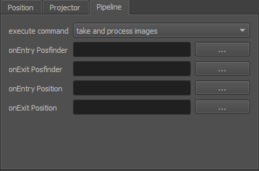
Pipeline Tab
These settings are adjustable in service mode only.
- Execute command
Control how images are captured and analyzed
- take and process images
Regular image capture and analyzing. (Default)
- fast take and process images
Take full dot pattern first, and check if it has moved. If it has not moved use old graycode images for processing, otherwise capture the complete image sequence again.
- take images
Capture images without analysis.
- process images
Analyze previously captured images.
- onEntry/onExit Posfinder
Optional scripts that are run before and after position finding is run. Each camera position has its own scripts. It can be used for example to control a rotation unit with camera mounted on top.
- onEntry/onExit Position
Optional scripts that are run before and after all the dot patterns of one position are captured. Each camera position has its own scripts. It can be used for example to control a matrix switch.
Collect Support Data
Calibration projects can get quite big, since all the captured camera images are kept for later use. While this is good to analyse and optimize the calibration offline this might be too much data to transfer over Internet.
Help/Collect Support File... allows to pack relevant project data in an archive that can still be
opened in Creator but has not the massive data masses produced during
image taking. It is typically requested from domeprojection.com for
support.
Service Mode
In order to avoid accidental reconfiguration of an alignment project, several settings are hidden during normal operation.
The service mode must be enabled to change and setup an alignment project.
The service mode gives access to:
Change Projector general connection settings
Creating new align projects from Creator projects
Adding and removing Camera positions
Exchanging cameras in an existing project
Configuring alignment process and automization
General project settings
Project Settings
Only available in Service mode. Use Help/Service Mode... to access Project settings in File
menu.
General
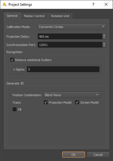
- Projection Delay
Allows to adjust the delay between showing testpatterns and taking images with the camera. Increasing this value might solve issues, with images taken too soon, but slows down the capturing process.
- Synchronization Port
This defines the UDP port for PatternGenerator feed back. It is used to sync the camera system to the PatternGenerator draw loop (/bufferSwap). Has to be the same as configured in PatternGenerator.
- Recognition
Global recognition parameters used for all channels and camera positions.
- Remove statistical Outliers
Removes points, that are significant more distant to their neighbors than the average distance between neighboring points in the camera image. (Statistical Outlier Removal)
- n Sigma
Points with distance to neigbours n-times standard deviation larger than average distance are removed.
- Generate 3D
When all testpatterns are captured, a 3d model of the projection will be generated. There are different strategies possible which have their pros and cons depending on calibration situation. The strategy and its settings can be adjusted here.
- Position Combination
Select how calibration patterns seen from multiple camera positions are combined.
- First/Last Occurance
Take the first or last capture of a dot.
- Average
Equally weight multiple captures of a dot to generate an average.
- Best Incidence Angle
Use only the capture with the best viewing angle (camera looking as orthogonal as possible on the screen surface).
- Blend Views / Incidence Angle
Dynamically weight multiple captures by regarding how central they where in the camera image and how orthogonal the camera was looking on the screen surface. (Default)
- Projection Model
Trace projection surface captured from initial calibration.
- Screen Model
Trace screen model.
- Fill
Fill parts that are missing during align with captured data from initial calibration.
Marker Control
Creator and Align can directly control active markers. These markers can be automatically detected by position finder (see section Position Finder)
Project Settings.../Marker Control allows to adjust the communication settings.
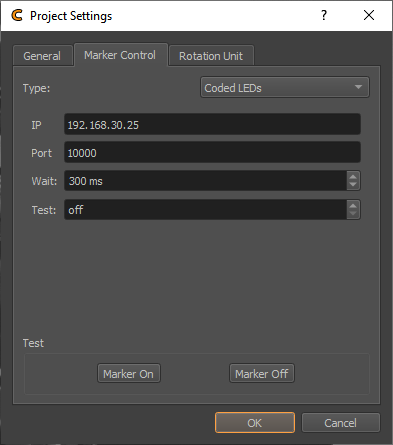
- Type
Type of marker control
- None
Marker control disabled.
- Manual
Request user to turn markers on and off.
- Script
Generic batch script to integrate custom automizations.
- Markers On/Off
Select the batch script that turns the markers on/off.
- Wait
Often it takes some time until the markers are actually switched, after the batch script returned. The delay can be adjusted here.
- Aviosys
Network controlled power plug.
- User / Password
Login required for this power plug. Initialized with factory defaults.
- IP
Network address of power plug.
- Port
Communication port used on power plug. Initialized with default port.
- Wait
Often it takes some time until the markers are actually switched. The delay can be adjusted here.
- Netio
Network controlled power plug.
- User / Password
Login required for this power plug. Initialized with factory defaults.
- IP
Network address of power plug.
- Port
Communication port used on power plug. Initialized with default port.
- Wait
Often it takes some time until the markers are actually switched. The delay can be adjusted here.
- Plugs 1/2/3/4
The netio support multiple power plugs. Select which plugs should be switched.
- Coded LEDs
Micro controller enabled LEDs supporting to control and identify each individual LED.
- IP
Network address of power plug.
- Port
Communication port used on power plug. Initialized with default port.
- Wait
Delay between setting the LEDs and capturing images.
- Test
Enable individual LEDs for testing purpose, and identification.
- URL
General interface for Network controlled power plugs.
- Markers On/Off
Select the URLs that turn the power plug on/off. Example on/off URLs for an Aviosys:
http://admin:12345678@192.168.0.5/Set.cmd?CMD=SetPower+P60=1
http://admin:12345678@192.168.0.5/Set.cmd?CMD=SetPower+P60=0
- Wait
Often it takes some time until the markers are actually switched. The delay can be adjusted here.
- 3D Disto
Leica 3D Disto. This measurement device with integrated laser pointer can be used to point at reference points of the project automatically. This works by finding its position relative to the project coordinate system and then pointing at the known 3d positions of reference markers in the project.
- Connect
Establish connection to 3D Disto software. Make sure 3D Disto software is running on the local machine and connection to 3D Disto established.
- Raw Rotation
Allows to rotate the 3D Disto in its native coordinate system.
- Transform
Defines the corrent position and rotation of the 3D Disto relative to Creators coordinate system. Use for estimating the transform based on an axis or three points.
- Wait
Waiting time between pointing at a reference point and taking images.
- TCP
General interface for any type of TCP/IP controlled devices.
- IP
Network address of marker control device.
- Port
Communication port of device.
- Marker On/Off
Network message to send for switching the markers on or off.
- Wait
Often it takes some time until the markers are actually switched. The delay can be adjusted here.
- Add Endline
Add endline control sequence to the message (\r\n) in case this is needed.
- Test Marker On/Off
Turn active markers on and off using current automization settings.
Rotation Unit
Creator and Align support cameras mounted on a motorized rotation unit, which is a common alternative to fisheye cameras and multiple perspective cameras for capturing screens with a large field of view.
For example, one perspective camera mounted on a rotation unit could cover a full 360 degrees cylindrical screen.
Project Settings.../Rotation Unit allows to setup and test communication with an installed rotation unit.
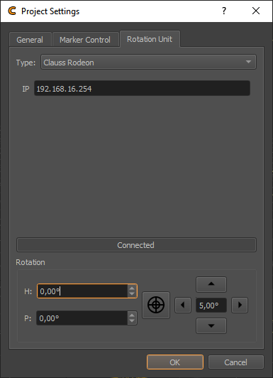
- Type
Type of rotation unit.
- None
No rotation unit available.
- Clauss Rodeon
Motorized rotation unit from Clauss, controllable over network.
- Connect
Connect to currently selected rotation unit. Allowing to test rotation.
- Rotation
Rotation control for currently selected rotation unit. This is for testing only. For setting permanent orientations use
Positions Editor/Position/Targetheading and pitch angles.
Build Align Project Wizard
Converts a calibration project for use in Align program.
Allows to select the original project and a new set of cameras from a given camera database. After conversion, the modified project is automatically opened in align and camera positions can be defined.
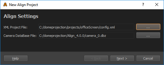
Select the project to be converted and the camera Database containing the align cameras calibration data.
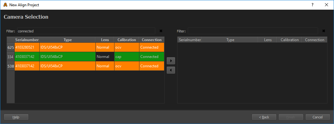
Select cameras in the left list that should be used in the align project. The list can be filtered for connected cameras, by enetring ”connected” in the filter.
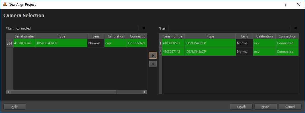
Add the selected cameras to the project using the right-arrow button.
The project can now be converted using the ”Finish” button. After that, the align program automatically opens the new project automatically.
Configure automatic Align
Configure automatic Align automatically selects projectors and adjusts dot patterns for camera positions.
It uses current camera position, orientation and opening angle information combined with initial calibration data, to predict, which projectors and which part of the dot pattern will be seen from that camera position.
Usage:
Add positions for each camera in Positions table and detect their position using Position Finder.
Than use Configure automatic Align.


