New Project Wizard
New projects can be created using Creators menu entry File/New Project....
A wizard will open and request all necessary information. A new project path with sub-folders and configuration project files will be created. Following subsections describe the available options on different pages of the project creation wizard.
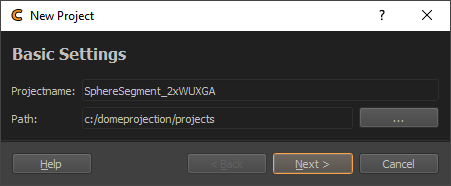
Basic Settings

Basic Settings
- Projectname
Name of the project. Subfolder with this name will be created.
- Path
Folder where the new project should be created (subfolder will be created, based on project name)
Screen Geometry
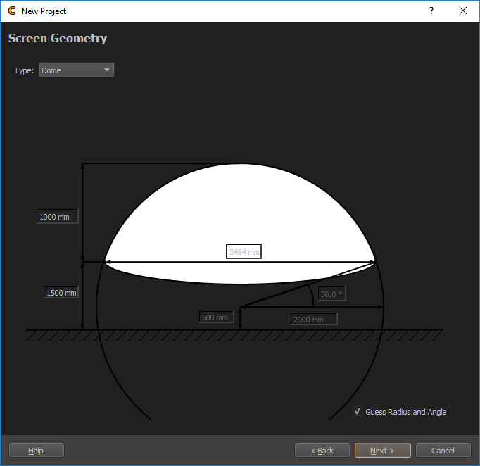
Here the screen type and parameters should be set up.

Screen Assistant
- Type
Select the screen type to be used.
Plane
Cylinder
Dome
Sphere Segment
Custom
- Angles and Radius
Design data for Cylinder and Sphere Segment screens. These are automatically generated when Guess Radius and Angle(s) is enabled.
- Distance Measures
Several distance measures such as width and height can be adjusted for each screen type. Some of these inputs are generated when Guess Radius and Angle(s) is disabled.
- Guess Radius and Angle(s)
Allows to enter measured lengths instead of angles for Cylinder and Sphere Segment screens. This is enabled by default.
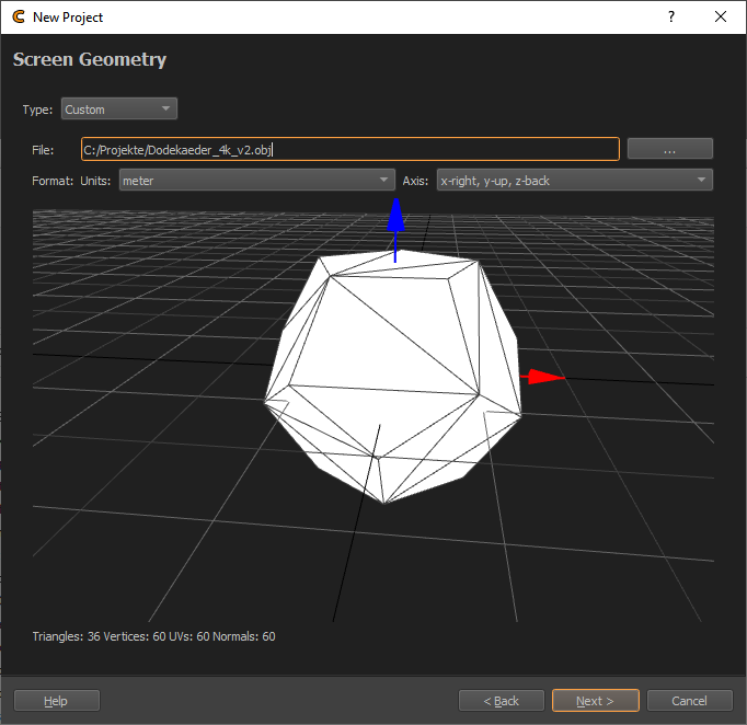
Depending on the license type it is also possible to import custom screen shapes from mesh files.

Screen custom
- File
Mesh file in one of the supported formats.
WaveFront Object (*.obj)
Stereolithography (*.stl)
Stanford Polygon Library (*.ply)
3ds Max (*.3ds)
AutoCAD DXF (*.dxf )
Autodesk (*.fbx )
glTF (*.gltf *.glb)
Collada (*.dae)
LightWave (*.lwo *.lws)
Modo (*.lxo)
Blender (*.blend)
- Units
Adjust units used in file.
- Axis
Select axis orientation used in file.
Channels Setup
During calibration, the Creator needs to project test patterns on all channels (typically, but not limited to projectors). On this page the type of pattern generation, the number of channels, their resolution and communication information can be set.

Projector Setup
By setting the “Channel Type”, ”Count”, ”Start IP”, Channels per IG” and resolution a list of channels is generated. The generated list of channels can be modified directly as well.
- Type
Interface to use for showing testpatterns.
PatternGenerator (default)
NDI
Norxe Unify
Barco Pulse
Luna
Warper4k
- Count
Number of projectors(channels) that should be calibrated
- Start Address
IP Address or name of pattern generating device used on first channel. In case of PatternGenerator usually the ip of the image generator pc attached to the first channel. In case of channel type Norxe Unify or Barco Pulse the IP of the projector. In case of NDI a name for the NDI stream. Number in Address is automatically incremented for additional Channels.
- Channels per IG
Defines how many channels are attached to each Image Generator (multiple channels in the generated list will get the same ip address).
- Resolution Width / Height
Channel resolution. The same setting will be used for all channels by default. If different resolutions are used in the system, the generated channels list can be modified.
- PatternGenerator use Channels
Activated by default. Should only be deactivated, if multiple PatternGenerator instances are running on one Image Generator (in that case multiple ports need to be used for communication).
- Slice Channels
Activate for channels, where pattern generation needs to be split across multiple pattern generators, but only one correction data set must be generated. For example multiple computers are attached to one projector and only one warping/blending set needs to be generated for each projector. Multiple standard configurations are available for selection.
- Generated Channel List
This list is automatically generated according to the setting above. The settings for each channel can be further modified in the list.
- IP Column
network address of computer where PatternGenerator software is running on
- Channel Column
channel number, used for PatternGenerator showing patterns for multiple projectors inside one instance
- Port Column
Port to communicate with PatternGenerator. By default 11000. If multiple PatternGenerator run on one computer different ports need to be used
- Width / Height Columns
Resolution of projector
Camera Selection
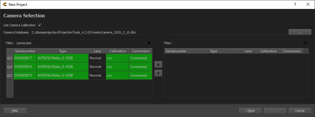
- Use Camera Calibration
Activate to use camera intrinsic calibration information (recommendet). If you have an uncalibrated camera, this must be turned off. Depending on this setting one of the following forms will be visible.
Calibrated Camera Selection
When ”Use Camera Calibration” is checked, a list of available camera calibrations will be shown.

Camera List
Here the camera/cameras can be selected, that should be used in the new project. In order to add cameras to the project do the following:
Select a Camera Database file, when not found automatically.
Select cameras in the left list
Use the right-arrow to add selected cameras to the right list
- Camera DataBase File
Database containing camera calibration informations. When camera database is placed in Installation folder, it is found automatically.
- Filter:
Allows to quickly find cameras in the list, e.g. by serial, type or connection state. Just enter the known information and the corresponding list is filtered dynamically.
- Cross
Quickly remove current Filter.
- Right-Arrow
Add selected cameras to project
- Left-Arrow
Remove selected cameras from project
Uncalibrated Camera Selection
When ”Use Camera Calibration” is unchecked, the following form will be shown.

Camera selection
Here connected cameras are shown and information about the used optics must be entered.
- Camera Dropdown
List of found, connected cameras, to select from.
- Refresh
Search for connected cameras again and update the Camera Dropdown list.
- Lens Type
Select between ”Perspective” and ”Fisheye”.
- Field of View
Shown for perspective lens type. The diagonal viewing angle visible on the camera image. This information is usually povided by the camera/lens manufacturer. Alternatively it can be calculated using the following formula:
FOV = 2*atan(0.5*diagonal / distance)
- Opening Angle
Shown for Fisheye lens type. The vertical viewing angle visible on the image, e.g. 180 degrees for normal fisheye fitting in the camera image.