Leica 3D DISTO
The Leica 3D Disto allows to measure 3d coordinates of reference points. The following sections describe how to capture data, that can be imported into ProjectionTools.
Preparation
There are some settings that need to be set in the 3D Disto software to make sure the export is compatible with ProjectionTools.
Setting |
Value |
|---|---|
Device…/Tilt Sensor… |
On |
Settings…/Language… |
English |
Settings…/Units…/Distance… |
0.000 m |
Settings…/Units…/Decimal separator… |
1.00 |
Settings…/Import/Export…/Format… |
East/North/Height |
Settings…/Import/Export…/List Separator… |
; |
Measurement with Room Scan
Mark coordinate system with two reference points (origin and one marker along x-axis). All markers will be measured relative to this coordinate system
start room scan application on Disto 3D tablet
set reference height to 0
measure reference center twice (once for reference height and once for origin)
measure second reference point on floor for definition on x-axis
measure markers (when using projected points from markermover, measure them in order of numbering so it makes finding points easier later in Creator Position Finder)
save data
export data to USB stick
Measurement with 3D Disto Ver. 4.0.5.0 and up
Mark coordinate system with two reference points (origin and one marker along x-axis). All markers will be measured relative to this coordinate system
start the 3D Disto software either on PC or the Leica tablet
measure the first marker point, it will become the origin of the reference frame
the first marker point will have reference height 0 by default
measure the second marker point for defining the x-axis
measure markers (when using projected points from markermover, measure them in order of numbering so it makes finding points easyser later in Creator Position Finder)
save data
export data to USB stick or hard drive
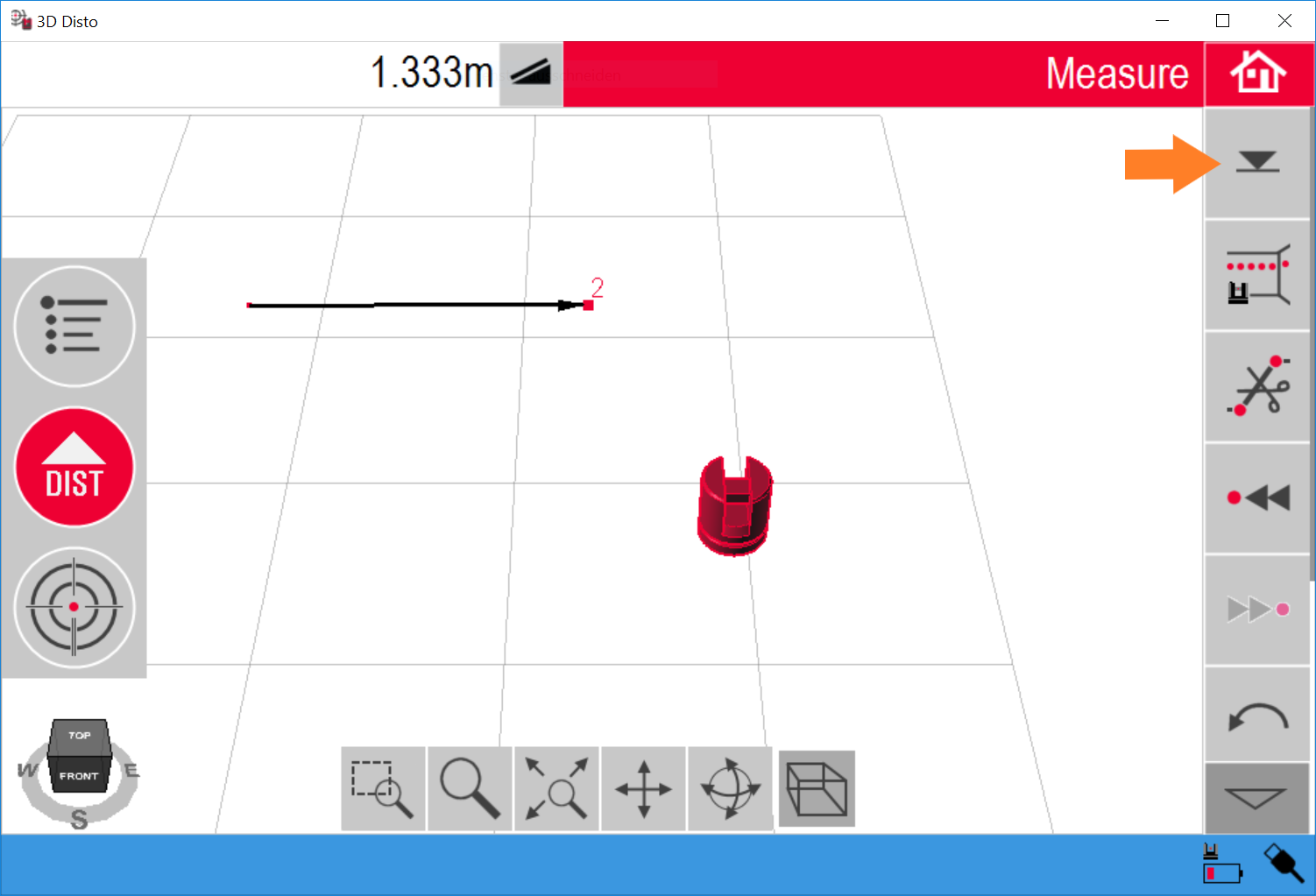
For setting a different reference height use the option in the world view (see orange arrow in fig. Setting the reference height in the Disto 3D software). When activated, enter the desired height and measure a point. This point will have the chosen reference height and the height of all other measured points will be adjusted accordingly.

Setting the reference height in the Disto 3D software
Repositioning
While usually not required, in some situations it might not be possible to measure all markers from one position. In such case it is possible to reposition the 3D Disto using the following steps.
Save current location using and measuring 3-5 points, that can be seen from current and next 3D Disto position. It is a good idea to mark these points visually, so they can be distinguished from each other.The 3d position of these points is measured and a snapshot is saved for each point for later reference.
Reposition the 3D Disto.
Wait until tilt check is finished.
Calculate the new 3D Disto position using .
A list of thumbnails is presented, from which points must be selected and remeasured.
After two measured points a check for precision follows, where the 3D Disto targets at the next Save Point. Please adjust the orientation of the 3D Disto if necessary and measure. The Disto will tell the result, if the precision is good enough.
If precision is good enough, accept the result and continue measurements. If Precision is not good enough, measure more save points.
Import Data in Creator
Attach USB stick to computer
Open Reference Points dock in Creator.
Hold “+” button below marker list and select “Import Leica 3D Disto” to import csv data from USB stick. Points should show up in marker list and 3d view