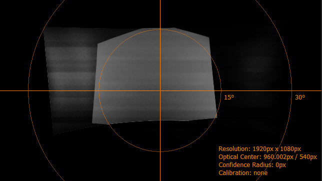
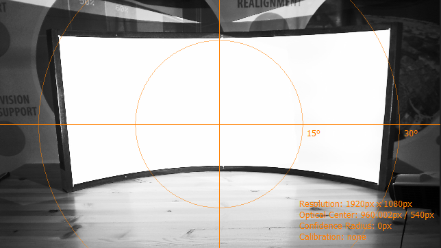
Calibration workflow
The Creator is used to capture the distortion of each projection image on the screen surface. In order to do that different dot patterns will be projected for each projector onto the screen while a camera will take pictures from that process.
The captured data is than used in Mapper2d, Mapper3d or MapperPM to define and preview content mapping on a screen.
The following sections describe the complete process from creating a new calibration project to showing a continuous warped and blended image on the screen using Mapper2d.
Preparation
Before starting Creator you have to make sure that:
Projectors are turned on and running for several minutes.
Image Generators connected to the Projectors producing an image in correct resolution.
PatternGenerator is installed, configured and running on all Image Generator computers.
A network connection between control computer and Image Generator computers is available.
The camera is connected to the control computer.
Create a new project
After opening Creator, create a new project by selecting File/New Project. The
New Project Wizard will open up and guide you through the process of
creating a new project.
Basic Settings
Enter a project name and select a path for storing the project on the first page.

Basic Settings
- Project name
Name of the project. A new folder with that name will be created and all project related data will be saved into that folder including a
config.xmlwhich can be loaded later for reopening the project. The demo version creates a
 config.ptdconfiginstead of aconfig.xml.- Path
The parent path (workspace) in which the new folder with the new project will be created.
Then hit next.
Screen Geometry
On the second page in the New Project Wizard define your screen shape. You can do this either by entering all screen design values directly or by generating some values from easy to take measurements.
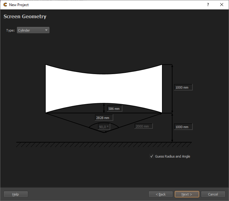
Screen Geometry
- Type
Select the screen type to use
 The demo version supports type Plane, Cylinder and Sphere Segment.
- Angles and Radius
Design data for Cylinder and Sphere Segment screens. These are automatically generated when Guess Radius and Angle(s) is enabled.
- Distance Measures
Several distance measures such as width and height can be adjusted for each screen type. Some of these inputs are generated when Guess Radius and Angle(s) is disabled.
- Guess Radius and Angle(s)
Allows to enter measured lengths instead of angles for Cylinder and Sphere Segment screens. This is enabled by default.
When you have finished entering the screen information, proceed to the next page by hitting Next.
Projectors Setup
On the third page in the New Project Wizard set the number of projectors used and their resolution as well as the IP-address of the Image Generator (Display Computer) where the projectors are connected to.
This allows Creator to project test patterns on the projectors using the PatternGenerator running on the Image Generator.

Projector Setup
 The demo version is limited to 3 channels and supports only a subset
of configuration possibilities.
- Projector Count
Number of projectors(channels) that should be calibrated
- IP
IP Address of Image Generator attached to projectors. You can read the IP address of the Image Generator in the info shown in the center of each projector by the running PatternGenerator.
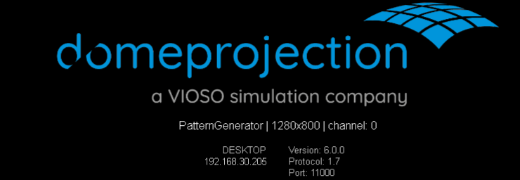
PatternGenerator infos
- Width / Height
Projector resolution. The same setting will be used for all projectors by default. If different resolutions are used in the system, the generated projector list can be modified.
- Generated Channel List
This list is automatically generated according to the settings above. The settings for each channel can be further modified in the list.
When you have finished entering the projection channel informations, proceed to the next page by hitting Next.
Camera Selection
On the last wizard page, select a connected camera to be used for calibration, then set its lens type and opening angle / Field of View.
 The demo version supports only uncalibrated cameras.
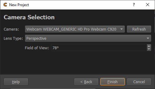
Camera Selection
- Camera Dropdown
List of found, connected cameras, to select from.
- Refresh
Search for connected cameras again and update the Camera Dropdown list.
- Lens Type
Select between ”Perspective” and ”Fisheye”.
- Field of View
Shown for perspective lens type. The diagonal viewing angle of the camera image. This information is usually given by the camera manufacturer.
- Opening Angle
Shown for Fisheye lens type. The vertical viewing angle visible on the image, e.g. 180 degrees for normal fisheye fitting in the camera image.
When you have selected the camera and entered its lens properties, you can create the project by hitting the Finish button. The wizard is closed, and you get back to the main window, with the newly created project.
Place and orient the camera
The camera life stream can be seen in the middle of the program window.
To make finding a good camera position easier, project a white test image using the preview toolbar.

Preview toolbar
The third button is used to project a white image for selected projectors, which makes it easier to detect the borders of the projection space. The fourth button is projecting the dot pattern, which is also a good pattern to position the camera.
In order to get a precise calculation of the projection surface, now find a good camera position and orientation that captures the whole screen. Typically this would be in the middle, in front of the screen, in a distance that allows to see the whole screen reasonable large in the camera image.
Adjust camera settings
Click on ”Settings…” below currently selected camera in Camera dock to open the Camera Settings dialog.

Cameras dock
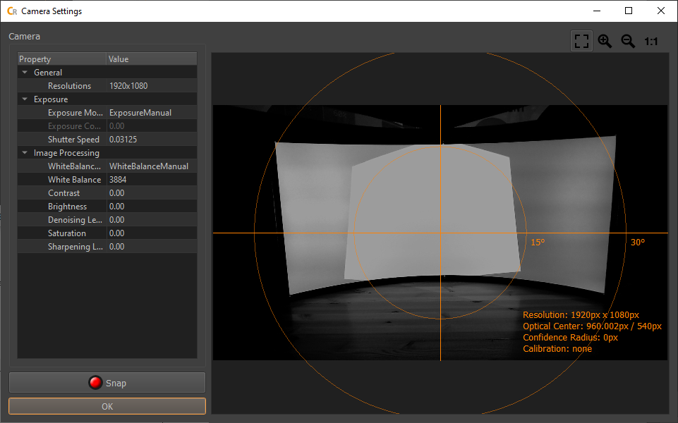
Camera Settings Dialog
The right side shows the last picture taken by the camera.
On the left are the settings available for your camera.
Use the settings on the left side of the dialog and update the camera image by hitting the Snap button, until the projection is clearly visible but not too bright.
When satisfied, you can close the dialog, by pressing the ok button. The live camera view now use your new camera settings.
Test pattern recognition
In the Projectors/Dot Pattern tab hit the button to open the recognition parameters dialog.
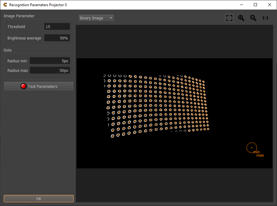
Recognition Parameters
After pressing Test Parameters the camera will take some pictures and Creator marks each detected dot with an orange cross.
All the points fully projected on the screen should be detected and marked with an orange cross. Cut dots projected on the screen border are usually not detected, that is intended behavior.
If not all of the fully projected points are detected, adjust the threshold and dot min/max radius and test the new parameters again to improve the detection.
By pressing ”ok” the settings can be saved and closed.
The recognition settings are adjusted per projector, so if the recognition settings needed to be changed, you might need to do the same for the other projectors.
Find camera position
We are starting the data capturing by calculating the exact camera position.
Double click on the camera serial number in the positions table or click
Position tab/Find Position... under positions table. This opens the
Find Position dialog.
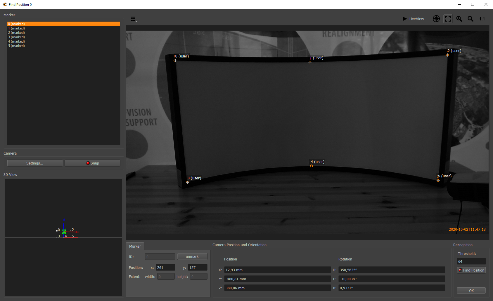
Find position dialog
The Position Finder is used to calculate the camera position and orientation based on reference points (markers) seen by camera.
 The demo version is limited to default reference points, generated at
the screen corners and the middle of the top and bottom edge of the
screen.
Usage:
Prepare lighting conditions. For simple passive feature points, such as screen corners, turn on lights or project a white testpattern using the projectors.
Snap an image.
If the feature points are not clearly visible, change camera settings using the
Camera/Settings...button on the left side of the dialog. Please note, that the Find Camera Position dialog uses a separate set of camera parameters.Select markers in the marker list on the left side and mark them in the camera image using double click.
Hit ”Find Position”.
When the calculation has finished, Camera position and orientation are updated (see position/orientation text boxes and 3d view). Also the recognized/defined markers and assumed marker positions in image based on projection of 3d markers are visualized in the camera image.
If problems occur, check if the markers are assigned to the correct position in the camera image and not exchanged. Another potential problem is, when you have not entered a correct field of view for your camera, when creating the project.
When camera position was successfully found, close Position Finder using ”OK” button.
Capture test pattern
After dotpattern, recognition and camera settings are adjusted, the image taking process can be started.
In order to take pictures select a complete camera position (click on camera id in positions table). This will automatically select all projectors for this position.
Than press “Take Images and Analyze” button on capture toolbar (second button from left side).

Capture toolbar
Different variations of the dot grid will be projected while the camera takes pictures.
After all pictures are taken the position table should update and visualize measurement result qualities. Green color means all projected points where detected. A tooltip shows the actual number of points projected and detected.
Double clicking on a cell in position table opens a picture showing the full dot pattern with added orange crosses. These crosses show which dots have been detected.
Missing points on the screen border and beyond the screen are fine. But you should aim for detecting all fully projected dots on the screen. Also you must avoid false positive detections.
Some missing points on the screen or false detections might be solved by simply checking your environment for movable obstacles or disturbing lights and removing them.
If you still have problems, see trouble shooting Calibration Troubleshooting to learn how to remove falsely recognized dots.
In rare cases not all dots are recognized after refining all camera settings, recognition parameters and masks, the rule for that case is, that at least 80% of the projected dots should have been recognized. The Mapper will then extrapolate the captured data, to cover the missing areas.
Generate projection geometry
When camera position is calculated and all projection patterns are
taken, use Capture Toolbar/Generate 3d (Cube) to reconstruct projection geometry from all captured
data.

Capture toolbar
When calculations are finished, a mesh for each selected projector is shown in 3d view.
The work in creator is finished and the project is ready for use in Mapper2D to show a preview of the result.
Save the project and close Creator now.
Preview calibration results
 The demo version of Mapper2d has no export functionality and supports
only the PatternGenerator for displaying content (with watermarks).
Start Mapper2d and open your previously created project using File/Load Project....

Mapper2d Preview toolbar. From left to right: Preview Black, White, Cutting, Warping, Shading, Fadeout, Uniformity, Grid, Image.
Select one of the following previews to visualize the results of your calibration.
Use preview grid to show a quick preview of a grid warped onto the screen.
Use preview image to select an image and show it warped and blended on the screen.
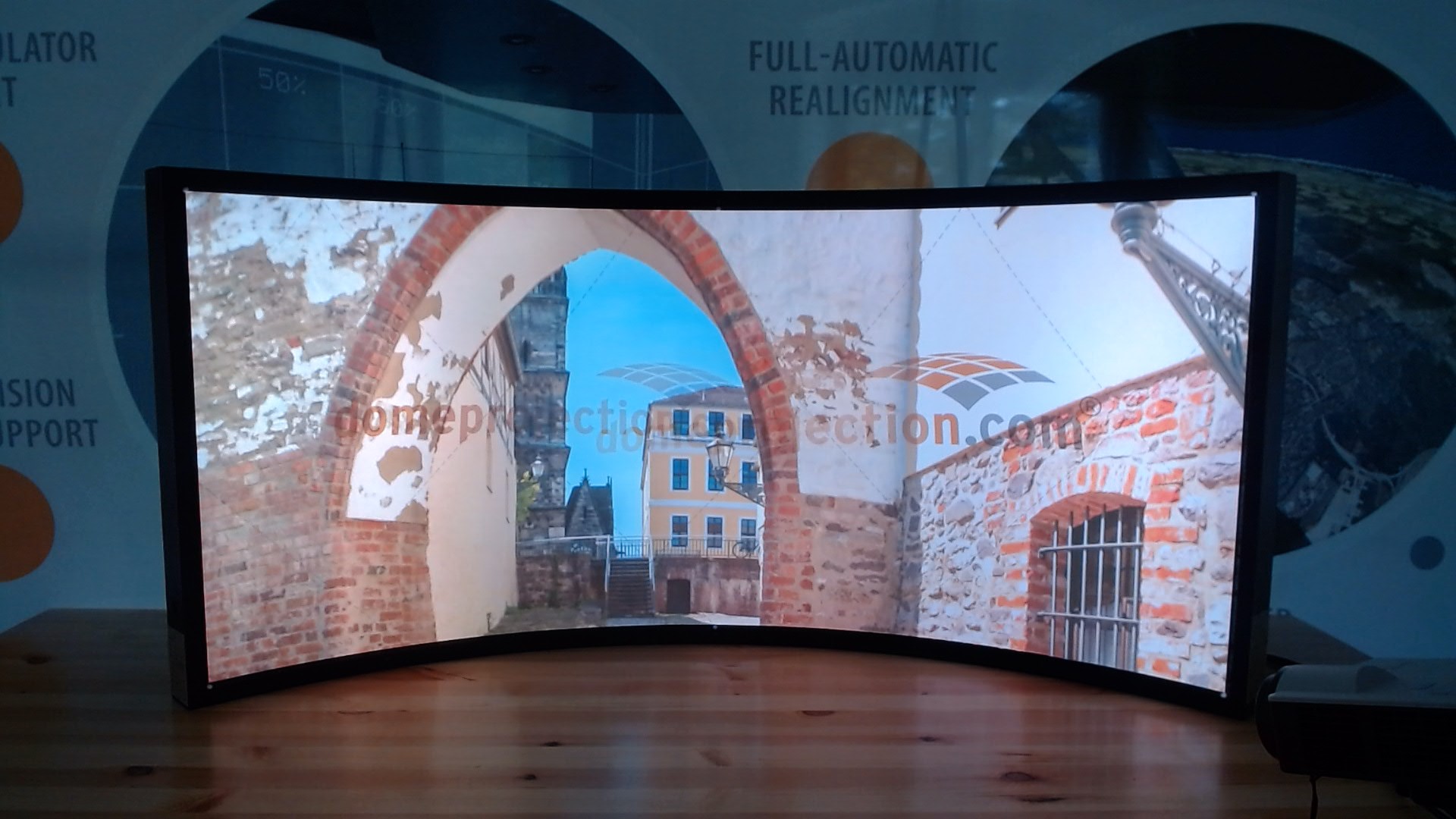
Mapper2d showing preview image on PatternGenerator
You have now finished your first calibration. From here you could take it a step further and do for example:
Adjust the mapping using the mapping editor, to adjust the outline or type of mapping.
Adjust fadeout and clipping of the screen, to match the screen border more closely.
Adjust the automatic uniformity correction percentage in
Settings/Shading/UniformityDisable blending calculation between distinct projection channels by putting projectors into different Blend Groups using
Projectors/Shading/Blend GroupAdjust cutting or clipping of individual projection channels and see how blending is automatically adapted.
