Mapping
The mapping projects the curved projection screen into 2d, it maps a 2D coordinate to any 3D coordinate on the screen. The 2D mapping of the projection, is used to define clipping and fadeout in 2d and for calculating the blending between projection channels.
By default, a mapping similar to the screen shape defined during project setup is used, but it can be fully customized and significantly differ from designed screen shape.
The Mapping dock allows to select and setup a mapping that best fits the screen and suits the content that should be shown.
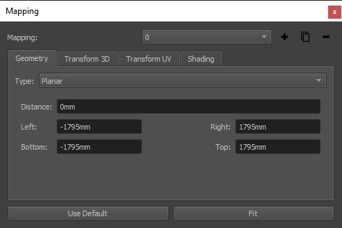
- Mapping:
- Selection:
If multiple mappings are defined in the project, select the current mapping for editing.
- Add Mapping:
Add a new mapping to the project.
- Duplicate Mapping:
Duplicate the currently selected mapping.
- Remove Mapping:
Remove the currently selected mapping. This is only possible when more than one mapping are present in the project.
- Geometry:
General mapping settings
- Type:
Select between standard mapping and reference mapping types.
- Type related Settings:
Settings for currently selected mapping type.
- Transform3D:
Place mapping in 3D-Space.
- Transform UV:
Transform resulting uv-coordinates (texture coordinates).
- Shading:
The shading-tab of the mapping-settings dialog allows to set several global parameters that influence blending calculations. (see section Shading for details)
- Use Default:
The Use Default button selects a mapping type and transform matching the screen settings that where defined during the calibration in Creator.
- Fit:
Fit the currently selected mapping to available calibration data by adjusting its parameters and Transform 3D.
Mapping Types
Several standard mapping types are supported plus one general mapping mode, that allows to import custom mappings.
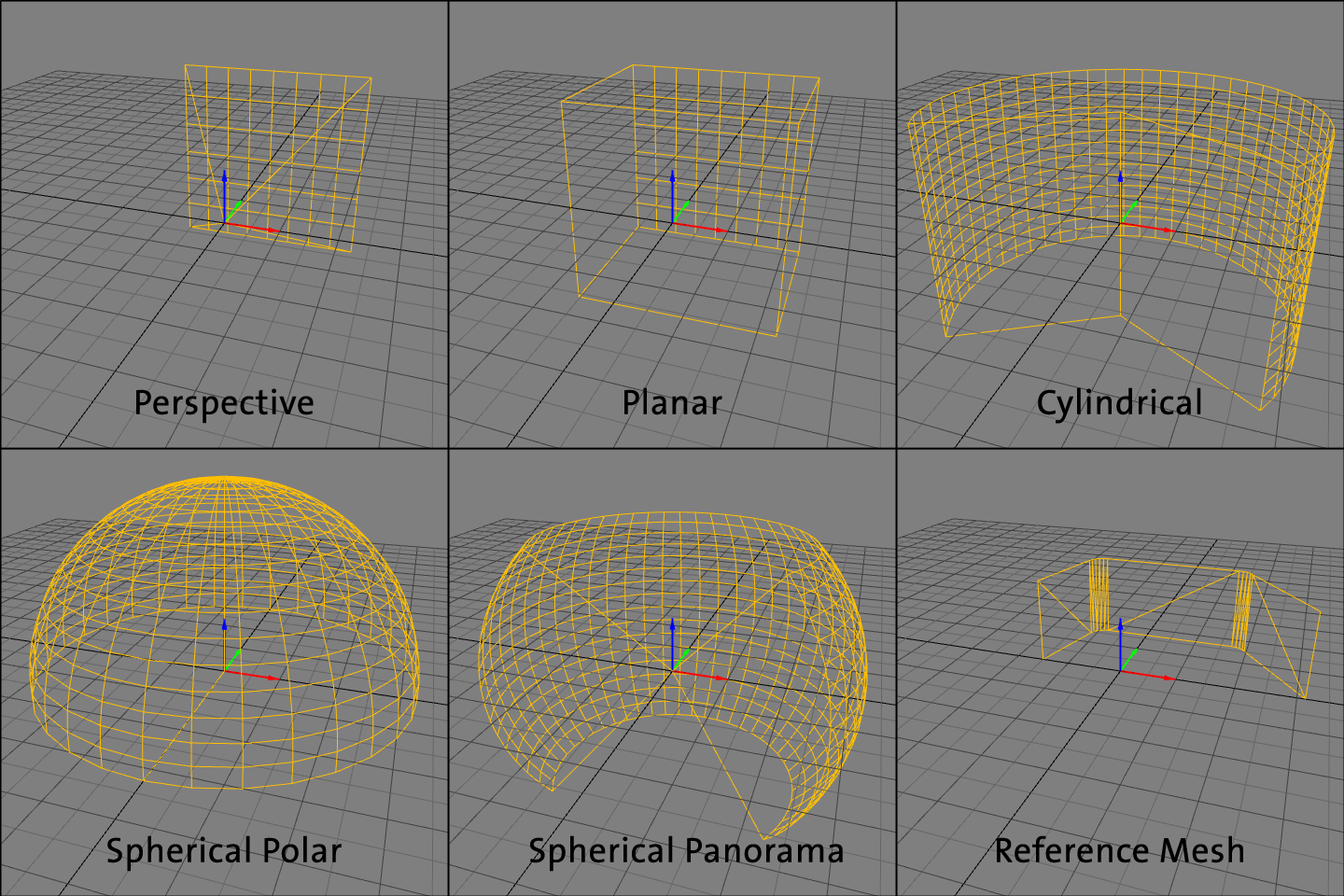
- Standard Types:
Standard mapping types are fast to setup and quite flexible to adjust in size, aspect-ratio and also their bounds.
- Perspective:
typically used to project imagery that is rendered using perspective virtual cameras. This produces perspective correct projections on curved screens for a designed eyepoint.
- Planar:
typically used for planar screens
- Cylindrical:
typically used for cylindrical screens
- Spherical Polar:
typically used to project domemaster files/ polar images on domes
- Spherical Panorama:
typical used to project panoramas on a sphere segment
- Torus:
Used for curved screens with two different radii in horizontal and vertical direction.
- Reference Mesh:
For very special screen shapes and projection layouts a standard mapping does not suffice. In these cases it is possible to define the mapping in an external 3D Modelling software, and import the mapping information in the form of a uv-mapped reference model.
The mapping type reference mesh allows to import such 3d geometry from external files (e.g. obj, stl, ply, 3ds). The reference model should contain only one mesh with a continuous uv-mapping. It is recommended, that the reference mesh is larger than the used screen, to ensure that mapping is defined for the whole projection area.
- Import:
Allows to import a mesh from external files (e.g. obj, stl, ply, 3ds). Coordinate transformations can be adjusted in a dialog during import.
- Export:
Allows to export the current mesh as obj file. Coordinate transformations can be adjusted in a dialog during export.
- Trace Mode:
Defines how 3d coordinates of measured projectors should be projected on the reference mesh to lookup uv-coordinates.
- Mesh Info:
Showing complexity and available data of current mesh.
- Generate UVs:
Generate simple planar uv-coordinates along one selectable projection axis.
- Generate Normals:
Generate vertex normals by interpolating adjacent triangle normals.
- Flip Faces:
Negates normals and flips triangles to point in opposite direction.
Shading
The shading-tab of the mapping-settings dialog allows to set several parameters that influence shading calculations.
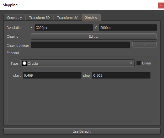
- Resolution X/Y:
Image width and height in pixels used for export blending source (unwarped). Also used for rastering of clipping data.
- Clipping:
Edit clipping in a separate editor. See clipping editor section.
- Clipping Image:
An additional image that will be multiplied with the calculated blending and vector based clipping.
- Fadeout:
Fadeout allows to limit the projection area to a rectangular or circular area.
The fadeout is previsualized in the 2d-view by a white outline marking the fadeout-start and a black outline marking the fadeout-end.
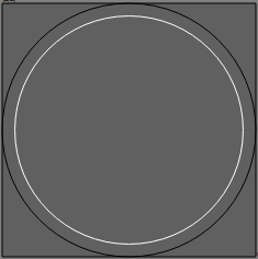
- Fadeout Linear:
Optionally set the fadeout falloff curve to linear, which make it usable for blending between multiple mappings (see section Multiple Mappings for details about using multiple mappings)
Multiple Mappings
Multiple mappings can be used to cover complete projection system. For example a full sphere could be covered with two polar mappings, or a projection on a cylindrical wall and the floor could be covered by using a cylindrical and a planar mapping.
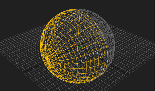
Each mapping has its own shading settings (clipping and fadeout), and each projection channel is assigned to one mapping.
In order to add new mappings use .
When multiple mappings are in the projects, each projector can be assigned to one mapping and a mapping selector appears in the mappings dock to select the current mapping.