Main window Overview

Default workspace
Creator has a fully configurable workspace. Above figure shows the default configuration with the typical widgets open.
- Menus
- File Menu
Create, Load and save projects. Adjust global project settings.
- Tools Menu
Additional tools and advanced operations on loaded project.
- View Menu
Workspace and theme management.
- Help Menu
Help, Support and Program information.
- Toolbar
The toolbar provides quick access to several preview and capture actions.
- Hardware
On the left are docks for all the components involved in the project listed.
- Projectors
The projectors dock widget shows a list of all projectors in the current project and allows to edit projector related settings.
- Cameras
Each project has at least one camera. In the cameras dock widget the cameras of a project can be viewed and their settings adjusted.
- Screen
Settings, describing the overall screen shape.
- Reference Points
Known 3d coordinates used for calculating camera positions.
- Camera view/3D View
In the center of the window is a camera-view and 3d-view available between which the user can switch.
- Positions
On the right side is the configuration of the calibration process visible.
All dock widgets can be arranged, stacked, opened and closed by user. The workspace layout is saved persistently.
It is also possible to revert to the default workspace using View/Default Workspace.
All available dock widgets can be found in the menu. They are described in the following sections.
The theme can be switched in View/Theme. An application restart is needed for a
theme switch to take effect.
For using the maximum workspace on the desktop, a full screen mode can
be enabled using View Menu/Toggle Fullscreen Mode.
Previews Toolbar

Preview toolbar
- Identify
show info on selected projectors
- Projector dark
make selected projectors black
- Projector light
make selected projectors white, others black
- Selected Projectors Gray
show dot pattern on selected projectors
- Project Codemarker
Show codemarker on all projectors. Press drop-down-button for more options (codemarkers, simple points, simple points with cross and label).
Capture Toolbar

Capture toolbar
- Take Images
Take test-image sequences with selected camera for selected projectors, without further image analysis. During capturing process, neither cameras nor projectors should be moved.
- Take Images and Analyze
Take test-image sequences with selected camera for selected projectors, and analyze images. During capturing process, neither cameras nor projectors should be moved.
- Analyze Images
Analyze images for selected position and projectors. This can be used to analyze previously taken images again after change of recognition parameters or masks. It is much faster than taking images again, and no attached cameras are required.
- Generate 3D
Reconstruct projection geometry by analyzing all images taken for projectors, camera positions and screen geometry information.
- Toggle Camera Connection
Enable/Disable camera connection. New images can only be taken, if camera connection is active.
Camera view
The camera view shows a live stream from currently active camera.
If the camera is turned off, switch it on using Capture Toolbar/Toggle camera connection
(see section Capture Toolbar).
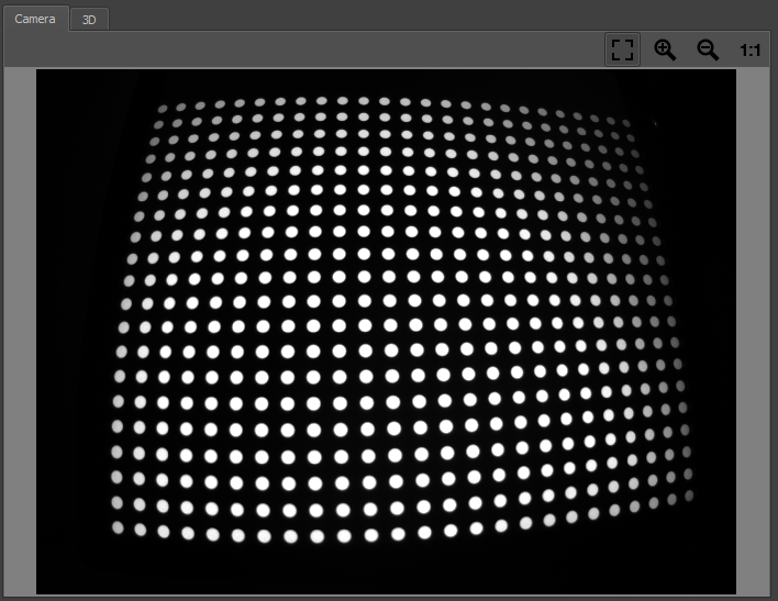
Camera View
- Navigation
The view can be dragged with the left mouse button.
- Scaling
Several scaling options are available at the top right corner of Camera View.
3D View
The 3D view provides a three dimensional overview of the current calibration setup.
This includes the theoretical screen, reference points, camera positions and measured projection geometry.
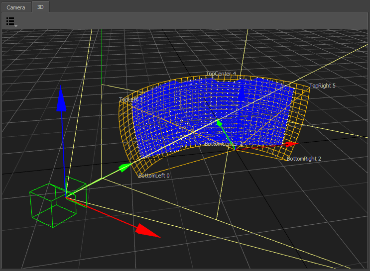
3D View
The current selection of projectors, camera position and reference points is regarded. Unselected elements are dimmed or hidden.
- Visualization Options
A drop down menu on the top left corner allows to select multiple visualization options.
- Screen
Theoretical/imported screen shape
- Reference Points
Imported/generated reference points
- Geometry
Generated 3d shape of each projector as mesh
- Measured Points
Measured 3d positions of captured points for each projector.
- Perspective
Switch to predefined orthographic views or the default perspective camera position.
- Navigation
Navigate the 3d view using the mouse.
- Rotate
Left mouse-button- Move
Middle mouse-button,Alt+Shift+LMB- Zoom
Right mouse-button,Alt+Ctrl+LMB
Project Settings
General
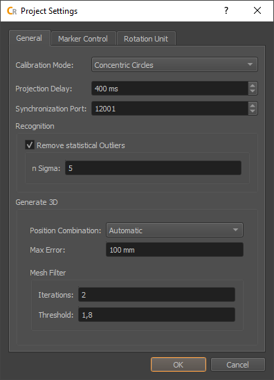
General Settings
- Calibration Mode
Defines what testpatterns are shown on projectors and captured by cameras to analyze the projection geometry.
- Classic Dot
A sequence of dot-patterns is used.
- Concentric Circles
In addition to the sequence of dot-patterns an image showing a ring for each dot is used. This allows to automatically detect cutted dots.
- Projection Delay
Allows to adjust the delay between showing testpatterns and taking images with the camera. Increasing this value might solve issues, with images taken too soon, but slows down the capturing process.
- Synchronization Port
This defines the UDP port for PatternGenerator feed back. It is used to sync the camera system to the PatternGenerator draw loop (/bufferSwap). Has to be the same as configured in PatternGenerator.
- Recognition
Global recognition parameters used for all channels and camera positions.
- Remove statistical Outliers
Removes points, that are significant more distant to their neighbors than the average distance between neighboring points in the camera image. (Statistical Outlier Removal)
- n Sigma
Points with distance to neighbors n-times standard deviation larger than average distance are removed.
- Generate 3D
When all testpatterns are captured, a 3d model of the projection will be generated. There are different strategies possible which have their pros and cons depending on calibration situation. The strategy and its settings can be adjusted here.
- Position Combination
Select how calibration patterns seen from multiple camera positions are combined.
- Automatic
Reconstruct a 3d surface using stereo vision, when possible (Triangulate). Parts that are only seen by one camera position or where camera positions are too close to each other are generated by tracing the screen and potentially blending multiple camera positions (Blend).
- Blend
Trace recognized patterns on assumed screen surface for each camera position separately. Than blend the resulting 3d positions of patterns captured from different camera positions. Use this option, when your camera is placed on one position and just rotated, not all parts of the screen are seen multiple times or the screen setting contains already an imported scan.
- Triangulate
Reconstruct a 3d surface using stereo vision, disregarding the assumed screen shape. Discrepancies between generated screen surface and assumed screenshape are color coded in the 3d view. Use this option when you plan to reconstruct the actual 3d shape of the screen-surface.
- Max Error
Maximum allowed error during triangulation. Triangulated points with larger error will be discarded.
- Mesh Filter
Generate 3D generates a point cloud first and then generates a mesh on it. This mesh can contain degenerated triangles. Degenerated triangles are usually stretched extremely along one direction. The mesh filter removes such degenerated triangles that have an noticeable longer edge length than the average triangles.
- Iterations
Number of iterations the filter is applied, or off.
- Threshold
Triangles with \(edge length > average * threshold\) will be removed.
Marker Control
Creator and Align can directly control active markers. These markers can be automatically detected by position finder (see section Position Finder)
Project Settings/Marker Control allows to adjust the communication settings.
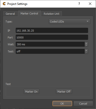
- Type
Type of marker control
- None
Marker control disabled.
- Manual
Request user to turn markers on and off.
- Script
Generic batch script to integrate custom automizations.
- Markers On/Off
Select the batch script that turns the markers on/off.
- Wait
Often it takes some time until the markers are actually switched, after the batch script returned. The delay can be adjusted here.
- Aviosys
Network controlled power plug.
- User / Password
Login required for this power plug. Initialized with factory defaults.
- IP
Network address of power plug.
- Port
Communication port used on power plug. Initialized with default port.
- Wait
Often it takes some time until the markers are actually switched. The delay can be adjusted here.
- Netio
Network controlled power plug.
- User / Password
Login required for this power plug. Initialized with factory defaults.
- IP
Network address of power plug.
- Port
Communication port used on power plug. Initialized with default port.
- Wait
Often it takes some time until the markers are actually switched. The delay can be adjusted here.
- Plugs 1/2/3/4
The netio support multiple power plugs. Select which plugs should be switched.
- Coded LEDs
Micro controller enabled LEDs supporting to control and identify each individual LED.
- IP
Network address of power plug.
- Port
Communication port used on power plug. Initialized with default port.
- Wait
Delay between setting the LEDs and capturing images.
- Test
Enable individual LEDs for testing purpose, and identification.
- URL
General interface for Network controlled power plugs.
- Markers On/Off
Select the URLs that turn the power plug on/off. Example on/off URLs for an Aviosys:
http://admin:12345678@192.168.0.5/Set.cmd?CMD=SetPower+P60=1
http://admin:12345678@192.168.0.5/Set.cmd?CMD=SetPower+P60=0
- Wait
Often it takes some time until the markers are actually switched. The delay can be adjusted here.
- 3D Disto
Leica 3D Disto. This measurement device with integrated laser pointer can be used to point at reference points of the project automatically. This works by finding its position relative to the project coordinate system and then pointing at the known 3d positions of reference markers in the project.
- Connect
Establish connection to 3D Disto software. Make sure 3D Disto software is running on the local machine and connection to 3D Disto established.
- Raw Rotation
Allows to rotate the 3D Disto in its native coordinate system.
- Transform
Defines the corrent position and rotation of the 3D Disto relative to Creators coordinate system. Use for estimating the transform based on an axis or three points.
- Wait
Waiting time between pointing at a reference point and taking images.
- TCP
General interface for any type of TCP/IP controlled devices.
- IP
Network address of marker control device.
- Port
Communication port of device.
- Marker On/Off
Network message to send for switching the markers on or off.
- Wait
Often it takes some time until the markers are actually switched. The delay can be adjusted here.
- Add Endline
Add endline control sequence to the message (\r\n) in case this is needed.
- Test Marker On/Off
Turn active markers on and off using current automization settings.
Rotation Unit
Creator and Align support cameras mounted on a motorized rotation unit, which is a common alternative to fisheye cameras and multiple perspective cameras for capturing screens with a large field of view.
For example, one perspective camera mounted on a rotation unit could cover a full 360 degrees cylindrical screen.
Project Settings.../Rotation Unit allows to setup and test communication with an installed rotation unit.
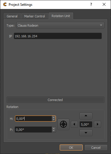
- Type
Type of rotation unit.
- None
No rotation unit available.
- Clauss Rodeon
Motorized rotation unit from Clauss, controllable over network.
- Connect
Connect to currently selected rotation unit. Allowing to test rotation.
- Rotation
Rotation control for currently selected rotation unit. This is for testing only. For setting permanent orientations use
Positions Editor/Position/Targetheading and pitch angles.