ATP Control

The ATP Control provides advanced test patterns usually required during Acceptance Test Procedure (ATP).
For showing the test patterns, the minimal requirement is only the PatternGenerator. So it comes in handy when the final 3D-Engine is not yet ready or does not provide such test patterns.
In order to come as close to the final 3D-Engine result as possible, the warping/blending solution of the visual system should be used. Only if such is not available (no warp unit, or warping driver) use the PatternGenerator internal Warping and Blending preview capabilities.
Since the test patterns are rendered independent of the finally used 3D engine it provides a good idea of the principal capabilities of the visual system but it does not fully replace a final check using the 3D engine to be used. The final 3D-Engine can differ in multiple ways. For example in effective resolution due to different filtering, or internal resolution. It can also differ in contrast and colors if additional tone-mapping is done inside of the engine.
Workflow
Some preparation needs to be done before the test pattern can bes switched quickly in ATP Control.
PatternGenerator must be running.
Enable potential external warping/blending solution.
Select according to current setup and desired preview quality.
Press Initialize - Button (System shows a simple cube map and is ready for quickly switching between ATP Test Patterns)
Show and switch between different test patterns.
Reset PatternGenerator when finished with ATP.
General Settings

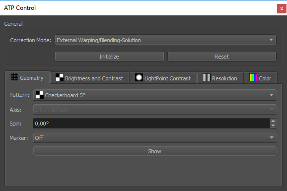
- Correction Mode:
Select how the geometry and blending correction should be handled.
External Warping/Blending-Solution
PatternGenerator internal - Rough (no blending, and black-level correction)
PatternGenerator internal - HighQuality (Advanced3D export options will be shown during next Initialization step for further options.)
- Initialize:
Prepares PatternGenerator for showing test patterns. Shows Advanced 3D export options, when is selected.
- Reset:
Switches PatternGenerator back to normal mode
Test Patterns
After system is prepared, the actual test patterns can be shown. These are grouped according to the usual display system parameters to be tested.

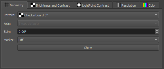
Geometry
Shows test patterns for checking geometrical quality.

- Pattern:
Selection of checkerboard and grid patterns in different resolutions.
- Spin:
Rotate pattern around major axis, for emphasizing potential discontinuities in warping.
- Marker:
Optional enable reference marker reprojection, for checking absolute precision. Marker size can be adjusted in degrees.
- Show:
Activate geometry pattern.
Brightness and Contrast
Shows a standard 5 degrees checkerboard grid on the whole system for measuring standard system contrast. The expected system contrast is much lower than the theoretical projector contrast, since it includes cross reflections in the system.

- Center Mark:
Shows an additional white rectangle in the center of each projection channel.
- Show:
Activate Brightness and Contrast pattern.
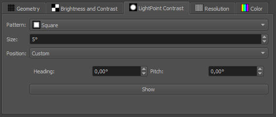
Light Point Contrast
Shows a single 5 degrees light point on black background by default. This allows to test the maximum contrast reachable in a visual system.

- Pattern:
Selection of multiple light point shapes.
- Size:
Size in degrees relative to current viewpoint.
- Position:
Allows to switch between
Custom (Default) single point on user defined position on screen (heading, pitch relative to current viewpoint)
Channel Center (one point at center of each projection channel)
- Show:
Activate LightPoint Contrast pattern.
Resolution
Shows optical linepairs according to a given optical resolution relative to current viewpoint. When all shown lines are countable on the screen, the visual system provides given optical resolution. This is the effective resolution including degradation of resolution due to warping.
Note
A visual system passes a resolution test, when all elements in the pattern are still modulated, not necessary black/white but dark/bright. The same number of lines should be elements on the screen (viewer can step close to the screen). When a different number of elements is counted, the test is not passed for that resolution.
Resolution test patterns can be used by either showing the required system resolution and check if the pattern is still shown correctly, or by starting with a low resolution (high arcmin/olp) and than gradually increasing the projected resolution (low arcmin/olp) until elements are not modulated correctly anymore and apparently fewer elements are projected.

- Pattern:
Select between multiple patterns
LinePairs: 48 horizontal and vertical line pairs (24 per sub-segment)
Points: 48 dots in a horizontal row
- Resolution:
Optical resolution of the testpattern relative to the current viewpoint in arcmin/olp (/element). Lower values mean higher resolution.
- Position:
Allows to switch between
Channel Center (Default): (one pattern at center of each projection channel)
Custom: single pattern on user defined position on screen (heading, pitch relative to current viewpoint)
Pixel Perfect: Pixel perfect at center of each channel. Warping must be turned off to work correctly! Can be used to count pixels on screen, measure size of pattern and calculate projectors optical resolution provided on screen (disregarding rest of visual pipeline).
- Orientation:
Rotates pattern around their center. Usually the effective resolution of the system increases for patterns oriented diagonal to pixel raster of projectors.
- Show:
Activate Resolution pattern.
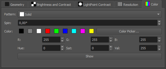
Color
Show uniform and optionally structured colors on the complete screen. This allows to test brightness and color uniformity for different colors.
Sometimes the uniformity changes when the base color is changed, this usually is caused by gamma or color-space problems in the projectors.

- Pattern:
Select between multiple patterns
Solid (Default): Unstructured solid color
Gradients: can reveal breakups in the gamma curve
Checkerboard 5 degrees: this pattern is sometimes required for uniformity measurements.
Clouds: some random smooth cloud structure
- Spin:
Rotate pattern around major axis, for moving the pattern through blendzones.
- Color:
Several ways for selecting and modifying colors from presets, over color picker to live controls.
- Show:
Activate Color pattern.