Modifier Stack
The modifier stack allows to manipulate geometric data with multiple modifiers in a non-destructive manner. The execution order of modifiers is from top to bottom.
In the global context of ProjectionTools Mapper it manipulates the calibration data generated by Creator on the fly.
This allows for multiple use cases, for example:
Adjusting the global coordinate system.
Correct for distortion of Mylar in collimated systems.
Mapping a realtime rendered 360 degree panorama on a flat wall.
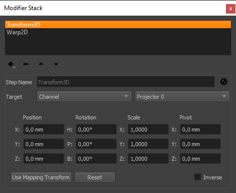
- +:
add a new modifier
- -:
remove selected modifier
- up arrow:
move selected modifier up
- down arrow:
move selected modifier down
- Step Name:
Each modifier can have a custom name.
- Disable Button:
Disable the selected modifier step (enabled by default).
- Target:
Each step can be applied to all channels (default), limited to a single channel or limited all channels on one mapping.
Several modifiers are available. Their usage and purpose is described in the following sections.
Transform3D Modifier
This modifier applies an affine transformation to geometry.
The transformation can be inverted as well. This is the default. It allows to remove a certain transformation, or make a certain position/orientation the new reference coordinate system.
It can be used for:
Removing an unwanted translation/rotation of the calibration data.
Making the designed eyepoint, the cockpit or any other coordinate system that is used by 3d engine the reference coordinate system. This way viewpoint offsets can be setup and exported in the same coordinate system, as the 3d engine is using.
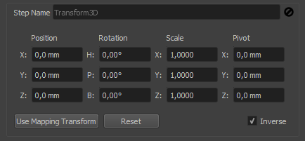
- Position, Rotation, Scale, Pivot:
adjust the transformation that should be applied or removed
- Use Mapping Transform:
Copy transform from currently setup mapping.
- Reset:
Set transform to identity again.
- Inverse:
Apply inverse transformation (remove transformation). Activated by default.
Warp2D Modifier
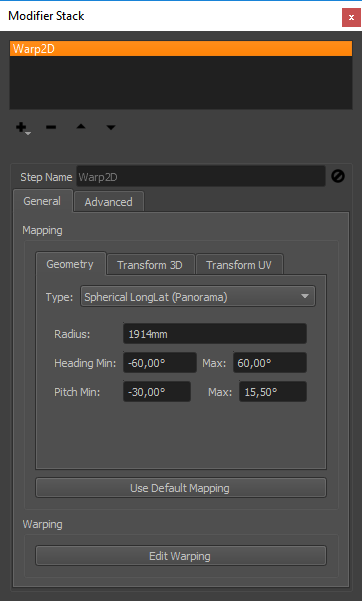
Allows to project geometry on a given surface (mapping) and warp along that surface.
It can be used for:
Let rectangular content follow irregular screen outlines.
Adjusting the projection on the BPS (Back Projection Screen) in a collimated system according to a reference slide-projector.
Adjusting the projection on the BPS in a collimated system to compensate the distortion of the Mylar.
Mapping
Before starting to work on the actual warping, the mapping should be setup correctly.
The Mapping group in the general tab allows to define this mapping, the surface where the geometry is projected on and warped along.
It has the same controls as the global mapping settings in Mapper, and usually the same settings should be used here, which can be done by pressing the button.
Warping
The warping editor can be opened using .
Beside the 2d view on the left side, where warping grid points can be dragged to adjust the warping, additional controls are available on the right side.
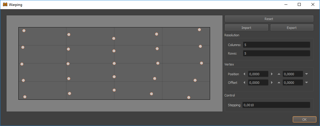
- Manipulate Warping:
Click on individual grid points to select them and move them by dragging the mouse.
Multiple points can be selected at once and moved simultaneously. For multi-selection hold Ctrl-Key or use rubber-band selection (drag out a rectangular area, where each point inside will be selected).
- Reset:
Resets the warping to zero. Current number of columns and rows is maintained.
- Import:
Allows to import warping in different formats.
- Export:
Allows to export current warping in different formats. These files can be imported again using the import functionality.
- Resolution Columns/Rows:
Allows to adjust the warping grid resolution. When the resolution is changed, the new grid points are interpolated using the current warping grid.
- Vertex Position/Offset:
Here the position and offset of selected grid points (vertices) can be viewed and edited numerically.
- Control Stepping:
Adjusts the step size for gridpoint manipulation. It is used in the numerical inputs, as well as for keyboard shortcuts and move buttons.
Hint
A live preview can be enabled, using ProjectorControl. Setup and show a grid preview in the desired resolution. It is a good idea to use a quite low resolution, e.g. 10 x 10 to speed up preview. Then activate .
Advanced
- Inverse:
Reserved for future usage: Inverts the warping. Enabled is the default. When applied to calibration data, this means the calibration data is warped inverse so that effectively any mapping will be warped forward as defined in the warping editor.
- Preview:
Allows to select between different preview modes.
- Import 3D Data:
Allows to import 3d reference points to define a warping. The reference points are projected using the current mapping to generate 2d coordinates. The points for import have to meet several criteria:
they need to be defined in the same global coordinate system that is used in the ProjectionTools project
the complete grid needs to be defined (no missing points)
the points need to be ordered linewise from top-left to bottom-right.
XLSX Format (exemplary excerpt):
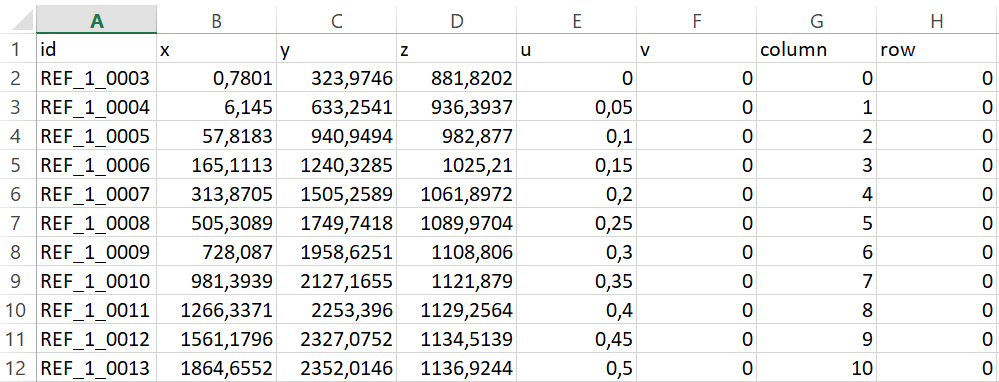
CSV / TXT Format (exemplary excerpt):
x;y;z;u;v;c;r
0.7801;323.9746;881.8202;0;0;0;0
6.145;633.2541;936.3937;0.05;0;1;0
57.8183;940.9494;982.877;0.1;0;2;0
165.1113;1240.3285;1025.21;0.15;0;3;0
...
3318.6295;1227.1266;-659.0816;0.85;1;17;6
3392.5252;971.2722;-677.8292;0.9;1;18;6
3422.868;690.7218;-697.1232;0.95;1;19;6
3407.542;430.5957;-713.4679;1;1;20;6
Remap Modifier
Allows to project geometry on one mapping surface and generate a new geometry along a second mapping surface.
geometry -> project on mapping A surface -> put on mapping B surface
It can be used for:
Rough adjustment of the projection on the BPS (Back Projection Screen) in a collimated system. For that purpose geometry can be projected on one spherical long-lat mapping and put on a second spherical long-lat mapping, that only differs in Transform3D rotation and heading and pitch min/max settings. For that purpose it works well to start with both mappings having the same settings, typically the default mapping, and than manipulating the input mapping A. This results in a direct manipulation of the resulting geometry. Manipulating Mapping B would result in inverse manipulation of the resulting geometry.
Wrapping realtime rendered content on any smooth surface with distorted perspective. For example, mapping a realtime rendered 360 degrees panorama on a flat wall, by mapping the measured screen shape from a planar screen to 360 degrees cylindrical and than defining virtual cameras looking around 360 degrees onto the cylindrical mapping.
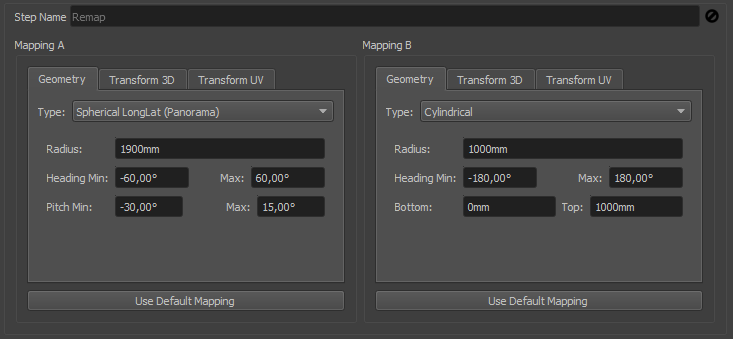
- Mapping A:
The mapping where the geometry is initially projected on. Controls are same as for standard mappings.
- Mapping B:
The target mapping, to which the geometry is transferred to. Controls are same as for standard mappings.
- Use Default Mapping:
Copy the settings from current mapping in project.
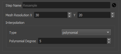
Resample Modifier
Allows to resample geometry to a defined full grid of m x n vertices.
It can be used for:
Before making complex geometry distortions or mappings it can be useful to increase the density of the initial geometry.
Original geometry might also have large undefined areas, which might be better to be filled in 3d space before doing the final mapping.
