Shading
Besides automatic geometry correction, ProjectionTools supports to adjust the shading of projection channels in several ways. The most important correction is automatic calculation of blending between multiple channels. Beyond that, several other corrections are supported, which are described in the following sections.
Blending
ProjectionTools can automatically generate blending information of arbitrary number of projectors overlapping in any way. In contrast to some other systems the blending information is calculated for each projector pixel individually. By doing so ProjectionTools is not depending on a grid layout of projectors with corresponding left, right, bottom and top edge blends.
Blending is calculated from captured geometry information. From that information the overlapping of projectors is known and a smooth transition between projection channels can be calculated.
For blending to work correctly it is critical to have a clean gamma-curve in the projectors and to use the same gamma for blending calculations (see section Shading)!
Often it is possible to select between gamma curves in the projector, but not all are clean gamma-curves. Some are optimized curves for increased contrast, that might not work for blended multi projector setups.
Possible problems:
- Blend zones are too dark:
Gamma setting in the project settings is lower than actual projector gamma. Either increase gamma in project or decrease gamma in projector.
- Blend zones are too bright:
Gamma setting in the project settings is higher than actual projector gamma. Either decrease gamma in project or increase gamma in projector.
- Blend zones are brighter or darker depending on content:
In that case the projector produces no clean gamma curve. You need to select a different gamma setting in the projector. If this is not possible you will not get perfect content independent blending with this projector.
Fadeout
In a multi channel projection system the uncorrected projectors usually project beyond the desired projection area (either the screen or a sub-area), broducing an irregular outline. For a finished setup the outline should usually be a clean smooth line following the physical screen edge.
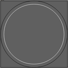
The fastest way to produce such clean outline is to activate a fadeout on the currently used mapping (see section Shading). This limits the projection to a rectangular or circular area.
The currently used fadeout is previsualized in the 2d-view by a white outline marking the fadeout-start and a black outline marking the fadeout-end.

While a hard cut off is usual, even wider smooth transitions can be generated with a fadeout setting.
The transition can either be standard to appear smooth or set to linear, which make it usable for blending between multiple mappings. For example to blend two polar mappings with an overlap to fill a complete 360° x 180° sphere screen.
For creating more complex outlines see following section Clipping.
In the exports, fadeout is usually encoded in the blend files, by multiplying blending and fadeout information. So it is naturally applied during runtime along with the blending and no special support is required.
Clipping
Sometimes the outline of a screen is irregular, there are openings in the screen or obstacles in the projection. These situations can not be covered by a standard fadeout anymore.
ProjectionTools provide a method for clipping such areas.
The clipping is adjusted in the Clipping Editor, which allows to draw vector shapes interactively on the screen (see section:ref:ClippingEditor).
The clipping is usually defined on the mapping for all projectors at the same time (see section Shading).
It is also possible to clip single projectors individually, such that these areas are projected only by neighboring projectors (see section Shading).
In the exports, clipping is usually encoded in the blend files, by multiplying blending and clipping information. So it is naturally applied during runtime along with the blending and no special support is required.
Brightness Uniformity Correction
The brightness of one projector might vary from one edge to the other possibly resulting from a non-orthogonal projection angle or curved screen shape.
ProjectionTools can compensate this brightness variation, by integrating a correction map in the exported blend-files. This way bright areas in the projector can be dimmed to reach the same level of brightness as the dark areas.
These brightness correction maps can be automatically generated by ProjectionTools. The automatic generation takes the stretching of the projected image into account which is usually the biggest reason for non-uniform brightness. (stretched parts distribute light on a bigger area and get darker. Shrunken parts focus light on a smaller part and get brighter)
There are two ways of generating the maps automatically:
Enable automatic global uniformity calculation in . It allows to adjust the degree of correction. 100% meaning full uniform brightness as the darkest point in the projection. 50% meaning brightness is reduced for all areas brighter than the medium brightness. 0% meaning there is no correction at all. Disabling the automatic calculation leaves the last calculated correction maps in the Brightness Adjust setting of each projector for further manual editing.
Use on a set of selected projectors. This is a one time calculation. Resulting correction maps are stored in Brightness Adjust setting of each projector for further manual editing. This feature can be used to compensate the uniformity of each projector separately. So that brightness differences between projectors can be adjusted in other ways, e.g. changing projector lamp-power or iris.
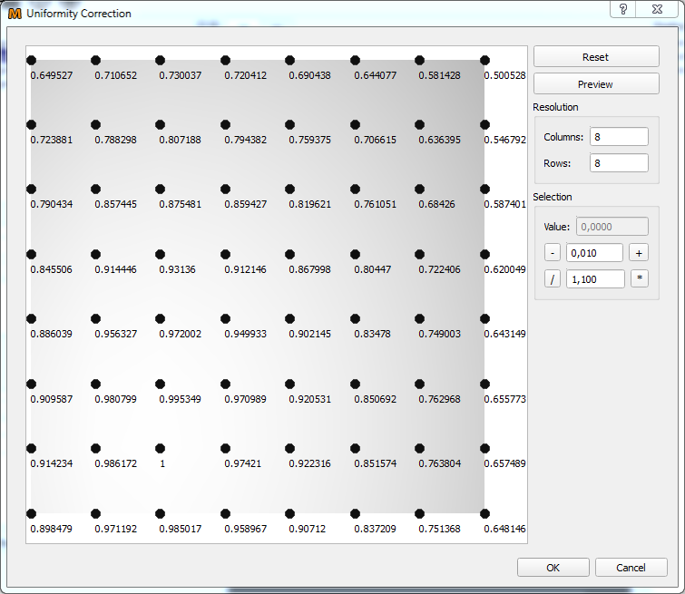
If global automatic generation of uniformity correction is turned off, Uniformity correction maps can be manipulated and viewed in the Uniformity Correction Editor (). See section Uniformity Correction Editor
In the exports, uniformity correction is usually encoded in the blend files, by multiplying uniformity correction and clipping information. So it is naturally applied during runtime along with the blending and no special support is required.
Warning
Be aware that software Uniformity correction potentially not only significantly reduces brightness of the projection. It also reduces the dynamic range of the image signal (reducing the number of available digital gray-levels).
Uniformity Correction Editor
Uniformity Correction Editor allows to manually adjust uniformity correction maps for each projector.

Be aware that brightness correction values are linear! Correction values around or below 0.5 are quite usual. Even if the preview looks already quite dark the result on the projector is probably far less visible.
- Reset:
Reset the grid resolution to 3x3 and all correction values to 1.0.
- Preview:
Show the current correction on PatternGenerator.
- Columns / Rows:
Changes the number of points that define the uniformity correction.
- Selection:
Allows to manipulate the values of selected grid points. Values can be overridden, shifted or scaled.
Tip
If a colorimeter is used for brightness measurements, the correction values can be directly derived from the luminance measurement differences.
Example:
Luminance measured on left side 22 (darkest part of the projector)
Luminance measured on right side 44
- The right side of the projector is two times brighter than the darkest part of the projector. So the correction for the right side should be 0.5.44 * 0.5 = 22
Black Level Correction
Projectors typically produce no perfect black. They expose still some light to the screen when the input signal is full black. In overlapping areas the resulting black level is even higher depending on the number of projectors overlapping. While this effect is neglectable for many media installations, it becomes disturbing in night scene content in planetarium and simulation applications.
A software black level correction can not remove the black level, but it can greatly reduce the heterogeneous appearance of the projection where overlapping areas stand out compared to non-overlapping areas. This is achieved by increasing the black level to one uniform level on the whole projection.
There are two calculation modes available, which can be switched and setup in (see also section Shading):
- Standard BLC:
A simple model for correction calculation, where user manually defines:
- Max Ovlerap:
Maximum number of projectors overlapping at any point. Typical is 2 for a linear setup of projectors in one row or 4 for a grid of projectors with multiple lines and rows.
- Black level:
The amount of light the projector exposes for black images. The corresponding preview can be used to help adjusting this value.
- Advanced BLC:
Automatically calculates maximum overlap and regards uniformity and projector clipping information. Brightness and contrast settings for each individual projector are used to calculate their actual brightness and black level distribution.
In the exports, black level correction is usually encoded separately, since special calculations are required to apply this correctly.
Note
Be aware, that several media servers and 3d-engines have none or only limited black level correction support.
Projector Shadow Removal
In some cases it might happen, that projector light is blocked by some obstacle. Usually at the edge of projectors in very tight setups. This is usually not an issue for normal day light blending, where the problematic projector is cut off before the shadowing begins.
For black level correction the shape and placement of this shadowing must be exactly known in order to compensate the missing black level using surrounding projectors. If the shadow is not compensated at all, there will be a dark hole in the projection of night scenes. If the shadow is assumed too big, there would be a bright area around the initial shadow.
ProjectionTools support the compensation of these shadows by allowing the user to define these shadows in each projector and later use that information during black level correction calculations.
Usage:
Select a single projector with shadowing in the projector list.
Open .
Draw a black shape matching the shadow in the projector.
Make a preview using Mapper3d Preview3d Exporter, with Black Level Correction enabled.
The drawn shadows will be used the next time you export black level correction. (Note: Currently the “useShadowMaps” option must be set in genericExporter configuration)
Tip
Invert the scene in Clipping Editor to draw a white shadow shape on a black background. This provides a good visual feedback during matching the drawn shape with the actual shadow. When the shape is finished, invert the scene again to have a black shape (shadow) on a white background again.