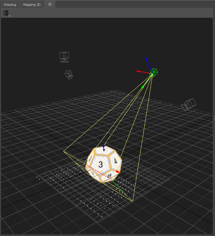
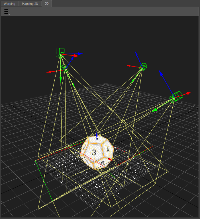
About MapperPM
The MapperPM program is used for managing all aspects of a projection mapping calibration and for exporting the results to the corresponding media server.
Based on any available calibration the following options are available:
calculating projector positions, orientations and frustum settings
calculating blending
calculating lens distortion
displaying test data on the mapped object using the PatternGenerator program installed on the image generator machines
exporting the correction data for different media servers or warp units/software
Basic workflow
The MapperPM takes previously captured calibration data and creates correction data for the projection mapping usecase. In that case the geometry projected on is typically discontinuous with complex uv-mapping.
The correction data created consists of:
projector positions, orientations and frusti
blending
lens distortions
The following chapters will explain how to calibrate a projection mapping system for the simplest case, in which the full 3d geometry including mapping of the object to project on is known in advance.
It is assumed that the reader has basic knowledge of capturing data with ProjectionTools Creator.
Requirements
A 3d model of the object to project on, including uv-mapping must be available during the calibration.
Capture Calibration Data
The Creator is used to capture the calibration data, using some settings to optimize the process for projection mapping.
Create a new project. Set screen type to custom and import the designed 3d model.
For meshes with low density a reference point will automatically generated for each vertex. If the screen model was too complex, markers need to be imported separately or manually added on the mesh surface using the
Points/Addmenu.Disable triangulate, since you want to ensure the calibration data lies perfect in the surface of the ideal 3d model, which avoids double imaging later, due to discrepancies of real and designed mapping object
Capture calibration data as usual with one or multiple camera positions
Store project
Preparing export in MapperPM
Load previously created project in MapperPM.
Hit
Mapping/Use Defaultto use the 3d-object imported into creator as screen as well for mapping content.In the 3D-View the object to project on and the projectors should be visible in plausible relative positioning. By default MapperPM is updating projector positions automatically.
Switch
Settings/Interpolation/General/Typeto spline, since for projectionmapping usually only a small part of each projector is captured and the generated warping needs to be extrapolated quite far and need to contain high frequent details.Hit
Preview Toolbar/Preview 3d warpedto project a quick preview of a checkerboard without blending.A high quality preview including blending can be shown, by adding a 3d preview to the Pipeline Editor.
Add one of the available exporters to the Pipeline Editor and export for the media server or 3D-Engine in use.
Main window overview
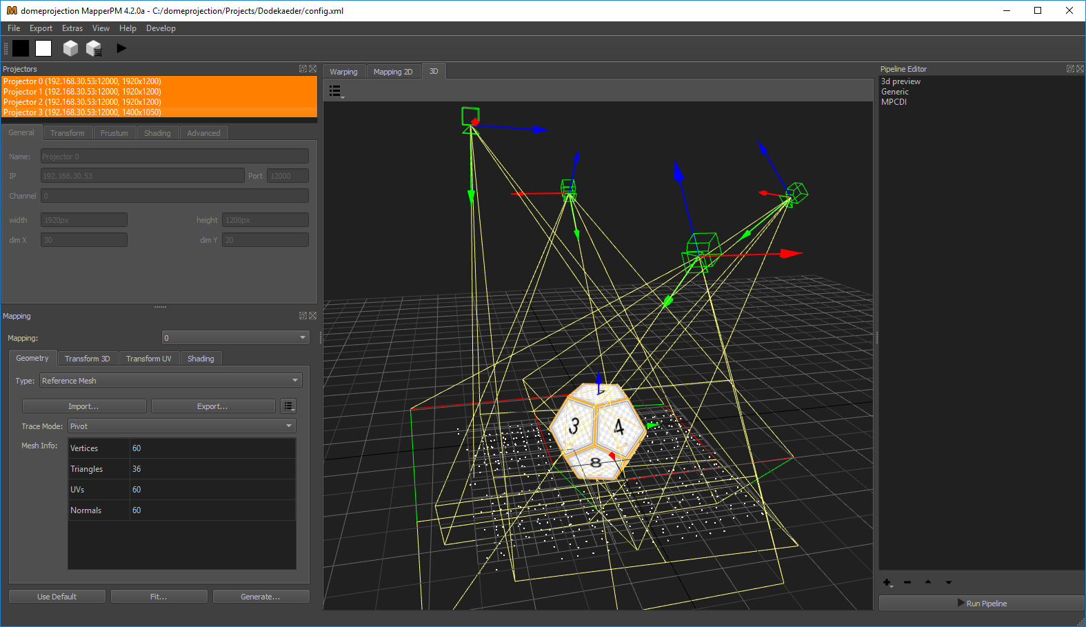
MapperPM main window
MapperPM has a fully configurable workspace. Above figure shows the default configuration with the typical widgets open.
- Menus
- File Menu
Load and save projects.
- Export Menu
Export calibration data from current project using available exporters. Please refer to section Exporters for a list of all available exporters.
Export settings used here are non-persistent. This is useful for experimenting with different settings, without changing a previously defined autoalignment work-flow for instance. Section Pipeline Editor describes how to save persistent export settings using the Pipeline Editor.
- Extras Menu
Additional tools and advanced operations on loaded project.
- View Menu
Workspace and theme management.
- Help Menu
Help, Support and Program information.
- Toolbar
The toolbar provides quick access to several previews and an automization run.
- Docks
Here a list of the most important docks, also shown in the screen shot.
- Projectors
The projectors dock widget shows a list of all projectors in the current project and allows to edit projector related settings. (see section Projector List)
- Mapping
Defines how image content should be mapped to the 3d object used to put content on the mapped object. By default it is a uv-mapped reference object. It is also possible to apply additional fadout and clipping. (see section Mapping)
- Pipeline
On the right side in the Pipeline Editor exporters can be configured with persistent settings to run multiple times. (see section Pipeline Editor)
- Central Views
In the center of the window are multiple views available between which the user can switch.
- Warping
Shows the warping between ideal and real projector of the currently selected channel.
- Mapping 2D
Shows uv-layout of currently selected Mapping, which is used to put 2d content on the mapped object and to define fadeout and clipping.
- 3D
Shows projection surface, mapping and projectors in a 3d view.
All dock widgets can be arranged, stacked, opened and closed by user. The workspace layout is saved persistently.
It is also possible to revert to the default workspace using View/Default Workspace.
All available dock widgets can be found in the menu. They are described in the following sections.
The theme can be switched in View/Theme. An application restart is needed for a
theme switch to take effect.
For using the maximum workspace on the desktop, a full screen mode can
be enabled using View Menu/Toggle Fullscreen Mode.
Projector List
There are different kinds of information stored for each projector. All values are managed by the tabs below the projector list, which apply to the selected projectors.

Projector list
The list shows the given Projector name, its IP address with port, the resolution and if an alignment is available (aligned).
The projector list is multi-selection enabled. Only selected projectors
are shown in the 2d- and 3d-view. Press Ctrl-A to select all
projectors at once or hold Ctrl- or Shift-key to add projectors to
current selection.
Projector settings can be edited when a single projector is selected, otherwise the projector settings placed below the projector list are grayed out.
General settings
First there are the general settings, which reflect the physical setup. Usually all data here is filled out in advance through the calibration process and its setup.
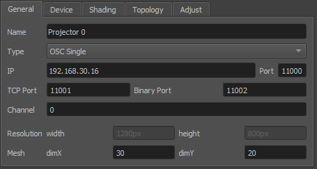
General projector settings
- Name
Human readable string describing the projector.
- Type
Interface to use for showing testpatterns.
- OSC Single
Default PatternGenerator based interface. Works with up to date PatternGenerator.
- OSC Multi
ProjectionTools channels are virtually split into multiple PatternGenerator channels. Works with standard PatternGenerator.
- OSC Legacy
Can be used for very old PatternGenerator installations, or installations on limited/embedded hardware. The preview functionality is limited.
- NDI
Provide testpatterns as one NDI-stream per channel. This can be used, if it is not possible to install PatternGenerator on the Mediaservers. Several Mediaservers support recieving and showing NDI-Streams. The preview functionality is limited.
- Norxe Unify
Send testpatterns as image directly to Norxe Unify projectors. This allows calibration without access to IGs.The preview functionality is limited, and not interactive.
- Barco Pulse
Send testpatterns as image directly to Barco Pulse projectors. This allows calibration without access to IGs.The preview functionality is limited, and not interactive.
- Luna
Send testpatterns as image directly to domeprojection Luna warp units. This allows calibration without access to IGs.The preview functionality is limited, and not interactive.
- Warper4k
Send testpatterns as image directly to Westar Warper4k warp units. This allows calibration without access to IGs.The preview functionality is limited, and not interactive.
- IP
Network address of the computer where the PatternGenerator software is running on. Hostnames are supported as well.
- Port
Networkport to communicate with PatternGenerator. By default 12000.
- Channel
The Channel is used to address a projector - if more than one is connected to a single PC.
- Width and height
Have to be the same as the physical projector resolution used in the projection and displayed here for reference only (not editable).
- dim X and dim Y
Attribute, defining the resolution of the warping grid. Larger values may gain better results but some constraints apply. There are hard limits depending on the warping unit. Bigger values are increasing the calculation time of many operations significantly, especially blend map calculation.
Transform and frustum settings
The transform and frustum settings define the physical position,
orientation and projection frustum of each projector. These settings are
generated automatically by default. When disabling Settings/General/Update Projector Positions these settings can be
adjusted manually.
The transform tab defines the position and orientation of the projector.
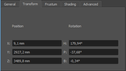
Transform
- Position (x,y,z)
The position relative to the center of the systems point of origin. Values entered in millimeter.
- Rotation (heading, pitch, bank)
Each projector can be rotated. The rotation order is:
heading
pitch
bank
The projection frustum is setup in the frustum tab. There are three different methods for entering/viewing the data. The method can be selected with the drop down menu (currently displaying Field of View).
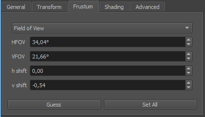
Frustum
- Input Method
Select method for viewing/entering frustum data. Changes input fields below accordingly. Options are:
- Field of View
enter the value in degree for the horizontal (HFOV) and vertical (VFOV) field of view. Shift the projection by fractions of 100 with h shift and v shift.
- Zoom
enter aspect ratio, zoom, h shift and v shift as fractions of 100.
- Separate Angles
enter the four (top, bottom, left, right) opening angles in degree relative to the middle point.
- Guess
The Guess button can be used to calculate the frustum and viewpoint orientation for the selected projector, based on the measured data. It is optionally possible to fix the current frustum and only update position and orientation of the projector. This makes calculation more stable when only limited depth information is available (projection on a flat area).
- Set All
Uses the current frustum for all projectors.
Shading settings
The Shading panel expose blending properties which can be different for each projector. There are other values as well, which apply to the whole setup and are adjusted in different places.
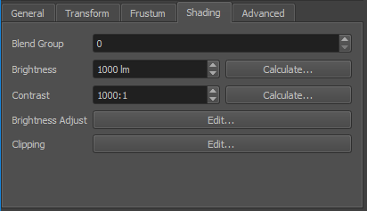
Shading settings
- Blend Group
In order to increase light intensity, sometimes two projectors are used to project on the same area of the screen. This is a so called “tandem” or “stacked” projection. Since blending is typically calculated between all overlapping projectors, the brightness of the tandem projection pair would be reduced to the brightness of one projector canceling out the initial intention of the tandem projection. The proper use of Blend Groups helps in this case.
Blending is calculated between projectors of same blend group only. Use different blend groups for different layers of projection or projectors between which no blending should be calculated. The blend group element assigns a projector to a blend group. The default blend group is 0.
- Brightness
Brightness of projector in lumen. Used for uniformity correction calculations.
- Brightness Calculate
Allows to calculate projector brightness from measured brightness of projected image center and a given screen-gain. Shows a small white rectangle on the selected projector center for taking a measurement right away.
- Contrast
Contrast of projector, used for advanced black level correction calculations.
- Contrast Calcutate
Allows to calculate projector contrast from black and white measured at center of projected image. Shows a black image and a small white image in projector center for taking measurements.
- Brightness Adjust
When global automatic uniformity correction is disabled, it allows to edit custom uniformity correction for a projector. See section Uniformity Correction Editor for details.
- Clipping
Allows to clip parts of the current projector. The clipped parts will be covered by neighboring projectors if present. It is usually used, if projectors are partly shadowed by obstacles.
Advanced projector settings
Additional not so common settings can be adjusted here.
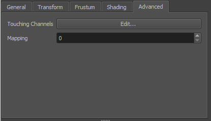
- Touches
Define the neighboring channels for high resolution projectors (See section Touching Channels).
Global settings
There are some properties that apply to the whole projection system. They can be modified in the settings tabs.
General settings
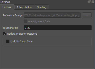
General settings
- Reference Image
An image that will be shown in background of 2d view and on mappings in 3d view.
- Use Alignment Data
If true, all further calculations are based on the data from the last auto align process instead of the initial calibration. The button is unavailable as long as there is not alignment data for all projectors stored in the database.
- Touch Margin
Allows to globally adjust touch margin for touching channels. See section Touching Channels for further information about high resolution projectors with multiple inputs and touching channels.
- Update projector Positions
When enabled, projector positions, orientations and frustum settings are updated when ever calibration data has changed. (Enabled by default)
- Lock Shift and Zoom
When enabled, only projector positions and rotations are updated. This makes calculations more stable when only limited depth information is available (projection on a flat area). (disabled by default)
Interpolation
Captured calibration data is usually incomplete and captured only for a finite number of points. For exporting correction data, Mappers need to interpolate and extrapolate this data for each pixel of a projector and maybe even beyond. Many mathematical strategies exist for that purpose, all with individual strengths and weaknesses.
For some projects, depending on screen and mapping type, it might be
necessary to switch to another interpolation type than the default. This
can be done in the global Settings/Interpolation tab.
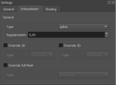
Interpolation Settings
Interpolations are used for different purposes in the project.
- General
For all purposes, if not overridden.
- Override 2D
Optional override for interpolations between 2d mapping and projectors (influences the grids seen in 2D view).
- Override full Mesh
Optional override for generating full meshes in 3d (influences full mesh visualization in 3D View and some advanced exporters)
Two interpolation types are available.
- Polynomial (Default)
Gives good generalization of general shape of warping with good exact extrapolation near measured data. Has the tendency to fold and generate wrong results far away from measured data. Has a degree parameter to adjust the complexity of warping. Lower values give better extrapolation results, but less fitting to details and strong curvatures.
- Spline
Gives better results for strong warpings and tight radii, or even sharp corners on screen. Generally captures details better, but has less generalization. More relaxed far distance extrapolation. Takes considerable more time to calculate!
Shading
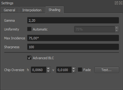
Global shading settings
The shading-tab of the project-settings dialog allows to set several global parameters that influence blending and black-level-adjust calculations.
- Gamma
Gamma of the projectors. Too high values will result in overexposed blending regions, a value that is too low will result in underexposed blending regions.
- Uniformity
Enable automatic global uniformity calculation. Allows to adjust the degree of correction. 100% meaning full uniform brightness as the darkest point in the projection. 50% meaning brightness is reduced for all areas brighter than the medium brightness.
- Max Incidence
Defines the maximum incidence angle up to which a projector is used for projection on a certain area on the projection surface. This avoids too flat projections where image of projector is weak and pixels are extremely stretched.
- Sharpness
Allows to gradually select between wide/smooth blending zones and hard narrow transitions between projectors. 1: smooth 100: hard.
- Smooth (1)
Usually good for smooth organic shapes.
- Hard (100)
Usually good for polygonal objects, where projectors are projecting from quite different angles, and effectively each projector is covering one or several facets on its own.
- Advanced BLC
Automatic overlap calculation and regarding uniformity information for black level correction calculations. Brightness and contrast settings for each individual projetor are used.
- Max Overlap
Maximum number of projectors overlapping at any point. Typical is 2 for a linear setup of projectors in one row or 4 for a grid of projectors with multiple lines and rows. (Non Advanced BLC only)
- Black level
Projectors typically produce no perfect black. They expose still some light to the screen when the input signal is full black. Black Level describes the amount of light the projector exposes for black images. The corresponding preview can be used to help adjusting this value. (Non Advanced BLC only)
- Chip Oversize
Projectors typically expose light to a larger area than the area of addressable pixels. These surrounding parts must be taken into account for black-level calculation. When they are not regarded, the edges of the overlapping areas will become apparently brighter than the adjacent areas.
- H/V
Horizontal/vertical oversize. Normalized values relative to channel width/height.
- Fade
Compensate for smooth black level spillover typically seen on LCOS projectors. Off by default.
- Test
Project dark triangles on each projector, supposed to line up with the borders of overlapping projectors. The preview regards global chip oversize, as well as potential overrides per channel. If there is a gap between triangles and overlapping projector decrease the chip oversize. If triangles are drawn partly on top of overlapping projectors increase chip oversize.
Warping view
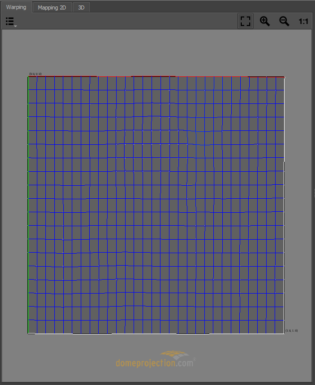
Warping view
The Warping view shows how 3D content rendered with virtual cameras is warped for each channel. The warping is represented as a distorted mesh in normalized projector chip coordinates ranging from (0,0) top-left to (1,1) bottom-right.
The red and green edge represent the top and left edge of the projector. The mesh is also colored depending on the estimated quality of the calibration. The quality gradient ranges from blue (very good) over green and yellow to red (bad).
- Visualization Options
A drop down menu on the top left corner allows to select multiple visualization options.
- Show Source
Shows the source grid.
- Show Target
Shows the warped grid.
- Show Vector
Visualizes the warping offset for each warping point, rendered as a white connection line between corresponding source and target coordinates.
- Navigation
The view can be dragged with the left mouse button.
- Scaling
Several scaling options are available at the top right corner of 2D View.
Mapping 2D view
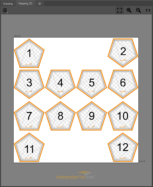
Mapping 2d view
The Mapping 2D View Shows the texture space, a normalized space ranging from (0,0) top-left to (1,1) bottom-right. It defines how 2d content is mapped onto the screen. This mapping is also used to define fadeout and clipping.
Selected projectors are shown in this view as a mesh. The mesh represents the region of the texture used for the corresponding projector. The red and green edge represent the top and left edge of the projector. The mesh is also colored depending on the estimated quality of the calibration. The quality gradient ranges from blue (very good) over green and yellow to red (bad).
- Visualization Options
A drop down menu on the top left corner allows to select multiple visualization options.
- Fadeout
In addition a visualization of the fadeout can be activated. The fadeout start and stop edge is marked by a white and black line. The fadeout can be adjusted in mapping settings, see section Shading for further informations.
- UV-Layout
A semi-transparent grid visualizing the area covered by the current mapping. This area is influenced by current mappings uv transform. Especially interesting for “Reference Mesh” mapping. See section Mapping for further information about mappings.
- Navigation
The view can be dragged with the left mouse button.
- Scaling
Several scaling options are available at the top right corner of 2D View.
3D view
The 3d view window shows the measured screen, mapping visualization and currently selected projectors in 3d space.
The current selection of projectors, and mappings is regarded. Unselected elements are dimmed or hidden.
- Viszalization Options
A drop down menu on the top left corner allows to select multiple visualization options.
- Mapping
Represents the current Mapping-settings. It shows the screen-shape and iconic projection-rays at the corners of the screen. In addition the projection of the measured points onto the screen are visualized.
- Virtual Cameras
shows a representation of currently setup virtual cameras. The camera frustum is rendered regarding cameras frustum settings and target distance.
- Projection
The measured projection can be visualized in three different ways:
- Measured Points
3d-position of measured points.
- Measured Mesh
Triangulation of measured points.
- Traced Mesh
Mesh traced from calculated projector position onto 3d scene.
- Perspective
Switch to predefined orthographic views or the default perspective camera position.
- Navigation
Navigate the 3d view using the mouse.
- Rotate
Left mouse-button- Move
Middle mouse-button,Alt+Shift+LMB- Zoom
Right mouse-button,Alt+Ctrl+LMB
Preview Toolbar
Several quick previews can be shown on physical screen, to assist during setup of blending, fadeout, ramps, mapping and easy camera.
The most often used previews have a button in the Preview Toolbar. Simply press a preview-button to show or update the corresponding preview.
Under Extras/Preview some additional previews can be found.
Note
Please note, that many preview images are results of simplified calculations and therefore not perfect. To judge the quality of a calibration a more time consuming preview export or an export into the real imaging system is needed.
Note
For the preview to work a PatternGenerator must be properly installed and running on each display computer. The warping is handled dynamically by PatternGenerator. If installed, warp units should not apply any blending or warping during the preview. Only exception is Preview 3D unwarped, this preview mimics a simple 3d engine where the rest of the correction needs to be done on an external warping solution.

Preview Toolbar
- Black
make all projectors black
- White
make all projectors full white
- Preview 3D
Render a simple cube map using currently setup virtual cameras. This preview is not warped. Warping on external warping solution must be activated.
- Preview 3D warped
Render a simple cube map using currently setup virtual cameras. This preview is already warped. Warping on external warping solution must be deactivated.
