Calibration Projects
ProjectionTools manage calibrations as projects. A calibration project is shared between all ProjectionTools applications, such as Creator, Align, Mapper2d and Mapper3d.
Each project is a folder containing a configuration XML file, calibration data and all pictures taken during calibration process. This project folder contains all relevant data and can be transfered between computers.
The project can be managed through the file menu:
- New Project
Creates a new project using the project creation wizard. (see New Project Wizard)
- Load Project
Loads an existing project. The project configuration XML file needs to be selected, which is placed in the main folder of each project. By default it is named
config.xml.- Recent Projects
Allows to reopen recently created or loaded projects.
- Save Project
The configuration of currently opened project will be saved.
The project contains information about the system components, the process and the calibration results. involved camera, screen-shape and channels involved.
- System Components
- Projectors
Information about projector resolution and testpattern generation and recognition.
- Cameras
The calibration cameras used to capture the testpatterns.
- Screen
The general shape of the screen.
- Reference Points
Measured or generated points for camera orientation.
- Marker Control
Optional control for active markers, that can be turned on and off automatically.
- Positions
The calibration process consisting of one or multiple camera positions.
- Results
A reconstructed point cloud and mesh of each projection channel, based on measured calibration patterns. It is visible in 3D View and used by Mapper2D and Mapper3D to calculate warping and blending for export.
These project components are described in the following sections.
Collect Support Data
Calibration projects can get quite big, since all the captured camera images are kept for later use. While this is good to analyse and optimize the calibration offline this might be too much data to transfer over Internet.
Help/Collect Support File... allows to pack relevant project data
in an archive that can still be opened in Creator
but has not the massive data masses produced during image taking.
It is typically requested from domeprojection.com for support.
For opening the support file again, unpack it (it is a zip archive) and than open it like a normal project.
The support project allows to see the complete calibration process including the result images, to check for errors.
It is not possible to process images again (e.g. for testing different recognition settings), since not all captured pattern images are available.
It contains all data required to use Mapper2D and Mapper3D for calculating warping/blending and doing exports.
Projectors
Projectors reflect one projection channel each. Usually one channel is used per projector. In some setups with 4k projectors, there might be more channels in the project than actual projectors.
The projectors dock widget shows a list of all projectors in the current project and allows to edit projector related settings.
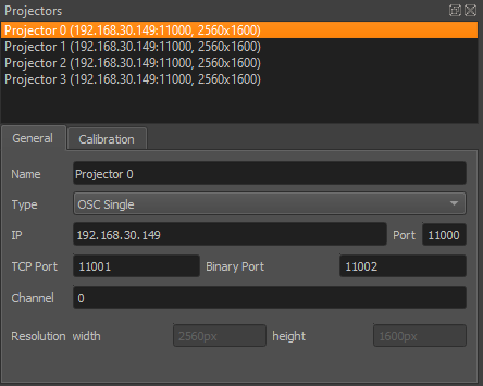
Projectors Dockwidget
List
A list shows all projectors in the project. Including name, ip, port and resolution.
This widget allows multi-selection of projectors.
Several other views in the application update according to the current projector selection.
Settings of currently selected projectors are editable in the tabs below the list.
Not all settings do support multiple projectors at once, these are grayed out when multiple projectors are selected.

Projectors list
General
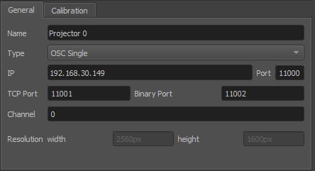
General settings
- Name
Arbitrary string describing the projector
- Type
Interface to use for showing testpatterns.
- OSC Single
Default PatternGenerator based interface. Works with up to date PatternGenerator.
- OSC Multi
ProjectionTools channels are virtually split into multiple PatternGenerator channels. Works with standard PatternGenerator.
- OSC Legacy
Can be used for very old PatternGenerator installations, or installations on limited/embedded hardware. The preview functionality is limited.
- NDI
Provide testpatterns as one NDI-stream per channel. This can be used, if it is not possible to install PatternGenerator on the Mediaservers. Several Mediaservers support recieving and showing NDI-Streams. The preview functionality is limited.
- Norxe Unify
Send testpatterns as image directly to Norxe Unify projectors. This allows calibration without access to IGs.The preview functionality is limited, and not interactive.
- Barco Pulse
Send testpatterns as image directly to Barco Pulse projectors. This allows calibration without access to IGs.The preview functionality is limited, and not interactive.
- Luna
Send testpatterns as image directly to domeprojection Luna warp units. This allows calibration without access to IGs.The preview functionality is limited, and not interactive.
- Warper4k
Send testpatterns as image directly to Westar Warper4k warp units. This allows calibration without access to IGs.The preview functionality is limited, and not interactive.
- IP
network address of computer where PatternGenerator software is running on
- Port
port to communicate with PatternGenerator. By default 11000. If multiple PatternGenerator run on one computer different ports need to be used.
- Channel
channel number, only used for PatternGenerator virtual where one PatternGenerator: instance shows patterns for multiple projectors
- Width and height
Have to be the same as the physical projector resolution used in the projection and displayed here for reference only (not editable).
Dot Pattern
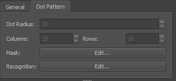
Dot pattern
- Dot Radius
Radius of projected dots in pixels. Might need to be changed depending on how big the points are seen in the camera image.
- Columns/Rows
Number of dot columns and rows.
- Mask Edit
Allows to edit the Dot Pattern.
- Recognition Edit
Allows to edit and test recognition parameters in an editor with visual feedback.
Recognition Settings
The recognition settings editor allows to edit and test recognition parameters with visual feedback.
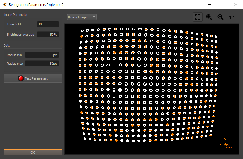
Recognition parameters
- Threshold
Circles are searched in the camera images. The search starts with binarisation and edge detection in the image. Threshold defines the binarisation threshold. The effect can be seen in the Binary image layer.
- Brightness average
Fades average image between black and white image. Pointcode detection uses the average image as adaptive binarisation threshold.
- Radius min/max
The minimum and maximum radius of dots in camera image in pixels. Only dots within this range are detected. When concentric circles are activated at
Project Settings/Calibration Mode, the inner and outer contour of the projected rings need to be in this range. The camera image contains an overlay in the bottom right corner, visualizing the current radius min/max setting.- Test Parameters
Take images with camera and show results. The Editor allows to show several images from the recognition process:
- Layer Selection
Select between multiple images showing different stages of the detection process.
- Black Image
First image taken with camera. Should contain no dots.
- White Image
Second image taken with camera. Should contain dots.
- Average Image
Average of Black and White Image
- Binary Image
Black/White Image. Dots should be full white, rest should be black, otherwise check threshold and camera parameters.
- Contour Image
Shows contours around each dot. Each dot should have exactly one closed contour.
Orange crosses are drawn on every detected point center.
Change projector Resolution
The projector resolution is setup during project setup in the project creation wizard (see section New Project Wizard). All calibration data is tied to that resolution, so that on a resolution change all data would need to be captured again.
To change the projector resolution select the projectors whose
resolution should be changed and use Tools Menu/Change Projector Resolution..., than capture and calculate all
calibration data again.
Cameras
Each project has at least one camera. In the cameras dock widget the cameras of a project can be viewed and their settings adjusted.

Cameras dock
- Combobox
Allows to select current camera for editing and showing its life stream. When adding new positions, the currently selected camera will be used for the new position. When selecting positions, this combobox will automatically update to the camera of the selected position (see section Positions).
- Add Camera
Adds another camera from a camera database to the project (see section Camera Database Browser).
- Remove Camera
Removes currently selected camera and corresponding positions from project. Only possible when multiple cameras are in project.
- Replace Camera
Replaces the currently selected camera. This will also update positions using the current camera to use the new camera. Please note, that all data captured with the old camera will be removed and need to be recaptured.
- i
Shows general information about selected cameras type and lens.
- Settings
Allows to adjust camera parameters in a separate Editor. See following section or further details.
Camera Settings
The Camera Settings dialog allows adjustment of camera settings, mainly in order to adjust the brightness of captured images.
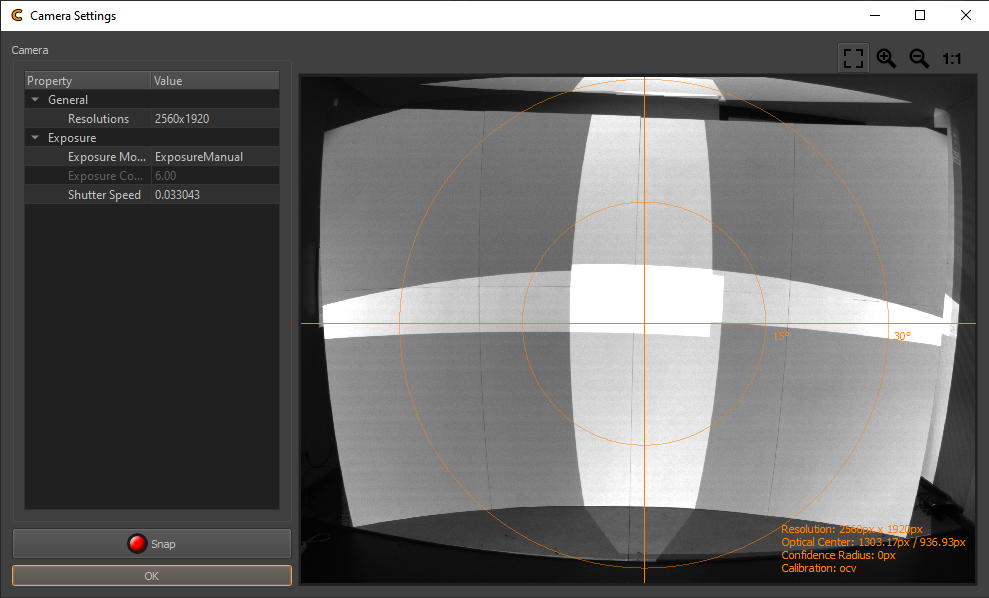
Camera Settings
- Parameters
The editable camera parameters depend on the camera type. Here a list of some typical parameters.
- Exposure
Settings influencing the brightness of the image.
- Exposure Mode
Select between manual and automatic exposure. Due to the type of image sequence we capture, it is advised to use manual mode, so constant camera settings are maintained during image capture.
- Shutter Speed
The time the shutter is open to take one image. Higher values result in brighter images
- Gain/ISO
Gain of camera signal, high values result in grainy images. Low values preferred.
- Aperture
Adjust the lens opening. Higher values reduce the lens opening and result in darker images.
- Focus
Settings influencing image sharpness and zoom.
- Focus Mode
Select between fixed and automatic focus. Fixed focus is highly recommended.
- Digital Zoom
Should be deactivated.
- Image Processing
Usually these settings should be deactivated.
- Snap
Capture a new camera image using current settings.
- Visualization
An overlay on the camera image visualizes the field of view and the principal point. Additional information about camera resolution and calibration is shown in the bottom-right corner.
The camera parameters should be set such that the projection is clearly visible but not too bright.
Camera Database Browser
The camera database browser allows to open and browse a camera calibration databases.
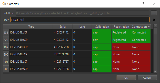
Its filter and sort functionality facilitates finding specific cameras, usually for adding them to calibration projects.
- General use
Open a database file, using the button on top-right corner
Search for a specific serial, type, or connection status using the filter or sort the database contents based on a data column by clicking on its header.
select one or more lines in the table
hit ok, for use of the selected cameras and their calibrations in a project
- Database
The camera database currently open. Open a new one using the open button on the right.
- Filter
An optional filter string. Text data from all columns is used. Wildcard (*) usage is supported.
- Type:
Camera manufacturer and type.
- Serial
Camera body serial number.
- Lens
Lens serial if known, otherwise 0 for perspective, 1 for fisheye lens type.
- Registration
Shows, if camera is registered to currently active license dongle. Only cameras registered to current dongle can be used for capture in Creator/Align.
- Connection
Shows if the camera is currently connected to the system.
Screen
The screen describes a theoretical screen shape. Information about the general screen shape is used e.g. for reference marker generation, calculating projection geometry and selecting a default mapping.
The screen information is entered using an assistant during project creation (see section New Project Wizard), but it can still be reviewed and adjusted in projects Screen dock widget.
Screen Editor

Screen geometry
- Select Screen
If multiple screens are defined in the project, select the current screen for editing.
- Add Screen
Add a new screen to the project.
- Remove Screen
Remove the currently selected screen. This is only possible when more than one screen are present in the project.
- Geometry
General screen settings
- Type
Depending on available license, select between different screen types
Plane
Cylinder
Dome
Sphere Segment
Mesh
Torus
- Culling
select on which side of the screen is projected. By default both sides are activated.
- Procedural Shape Settings
The standard shapes like Plane, Cylinder, Dome and Sphere Segment are procedurally generated. Their shape can be further adjusted using parameters to adjust their size and outline.
- Mesh Settings
The mesh is usually imported from obj files generated by external software (scans or designs).
- Import
Import a mesh from external files (e.g. obj, stl, ply, 3ds). Coordinate transformations can be adjusted in a dialog during import.
- Export
Export the current mesh as obj file. Coordinate transformations can be adjusted in a dialog during export.
- Mesh Info
Showing complexity and available data of current mesh.
- Generate UVs
Generate simple planar uv-coordinates along one selectable projection axis.
- Generate Normals
Generate vertex normals by interpolating adjacent triangle normals.
- Flip Faces
Negates normals and flips triangles to point in opposite direction.
- Transform 3D
Place screen in 3D-Space. Screen-geometry can be positioned, rotated and scaled. X, Y axis lying on ground, Z-axis pointing upward.
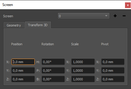
Screen transform
Screen Assistant
The screen assistant allows to setup screen geometry based on simple input values on top of a graphical representation.
It is available in Menu/Tools/Screen Assistant.
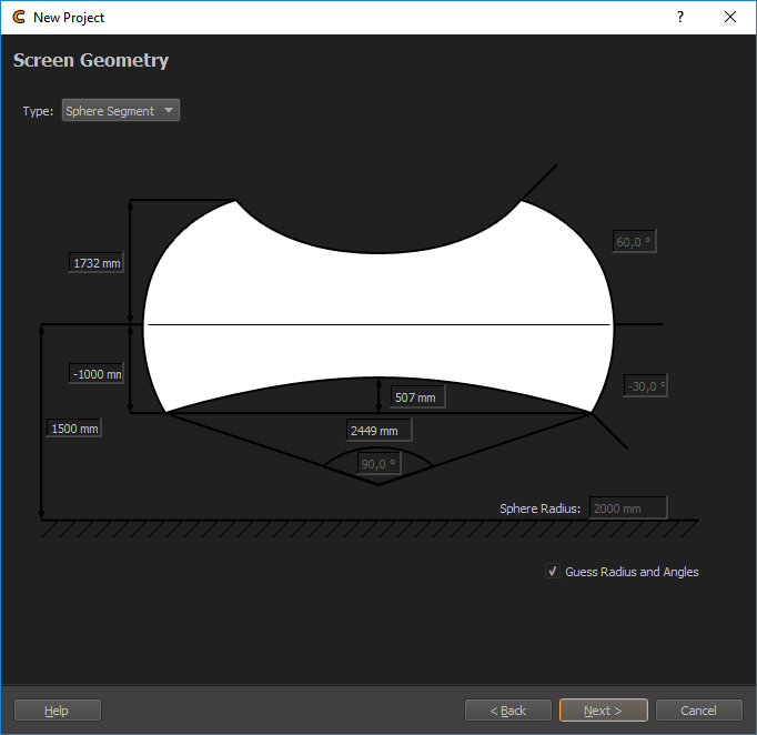
Screen assistant
The screen assistant supports the following screen types:
plane
cylinder
dome
sphere segment.
Screen Fitting
The fitting dialog allows to automatically calculate screen parameters based on measured points on the screen-surface.
It is available in Menu/Tools/Screen Fitting.
For the calculation the general screen type is necessary (automatically set, based on the project), and a set of points (by default reference points currently available in the project).
Note
Reference points usually have some additional points in the list, that are not lying on the screen surface. These points must be removed from the points list in the fitting dialog before fitting the screen.
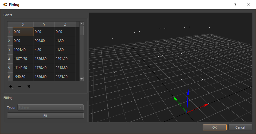
Screen Fitting Dialog
- +
Import points (multiple formats available)
text file containing one point coordinate at each line ([id] x y z)
Leica Disto 3D csv export
obj file
- -
remove selected points (only points on the screen surface should be contained in the list, If there are additional points in the import, these must be removed)
- x
Clear the complete point list
- Fitting Type
Shows the general screen-type (detected from project, either plane, cylinder or sphere)
- Fit Button
Fits the screen-geometry to markers
Reference Points
Reference Points are known 3d-positions. They are usually related to visually detectable features, such as screen corners or any type of marker such as LEDs or Laserpoints.
They are used to calculate the position of calibration cameras (see section Position Finder) and give calibration results a scale and relation to the real setup.
A default set of reference points is generated on project creation, based on screen information given (see figure Reference Points Visualization in 3D View). This is usually sufficient for single camera position calibrations. For calibrations involving multiple camera positions, exact measured markers should be imported.
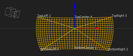
Reference Points Visualization in 3D View
The reference points editor allows to view, generate and edit reference points.
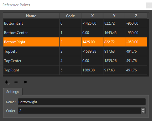
Reference Points editor
- List of Points
The list shows all reference points in the current project with their related 3d-position. Select points in this list for editing, removing or highlighting in different views.
- List of Points Context Menu
A context menu allows to manipulate marker selection and manipulate multiple selected markers at once.
- Index to Codemarker ID
Convert continuous index codes to CodeMarker IDs. Allows to apply an index shift, e.g. if the Reference point with code 3 should be the first Codemarker (with Codemarker ID 32), apply a shift of -3.
- Shift Codes…
Add/removes given value to codes of selected markers.
- Select New Markers
Selects reference points that are marked as new. These markers are not yet used for position finding since their own position is not yet calculated or valid.
- Add Points (
 )
) Opens a drop-down menu with several options to add markers:
- Add single Marker
Allows to manually add a single marker at a user defined position.
- Generate Markers
Generate reference points based on the ideal geometrical shape of the screen. This is usually sufficient for single camera position calibrations, but not recommended for multiple camera position calibrations.
- Procedural
For standard shapes like Plane, Cylinder, Dome and Sphere Segment a selectable number of marker rows and columns are generated automatically. Their shape can be further adjusted using parameters to adjust their size and outline.
- Mesh
For low-poly meshes (up to 100 triangles) the reference points are generated automatically at each vertex.
For larger meshes, a dialog opens, that allows custom placement of markers on the current screen mesh, by clicking on the mesh in the 3d-view (snaps to close vertices).
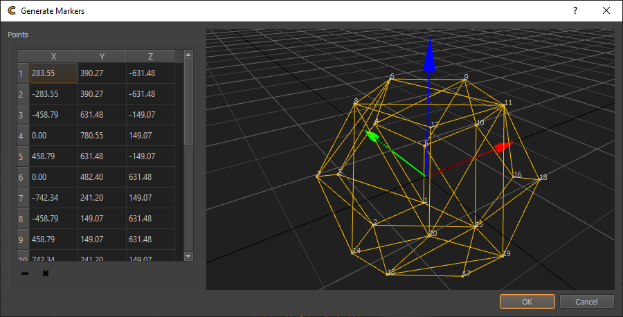
- Add new Markers
Add a selectable number of new markers, that are marked as new. These can be triangulated later, to calculate their actual position.
- Import Leica DST 360
Import a proprietary format generated by Leica DST 360.
- Import Leica 3D Disto
Import a proprietary format generated by Leica 3D Disto. Please see appendix Leica 3D DISTO for details.
- Measure Leica 3D Disto
Measure points directly using a custom dialog and a Leica 3D Disto connected to the computer. See Pointer 3D Pointer 3D for further details.
- Import Leica Nova
Import a proprietary format generated by Leica Nova (MS50).
- Import Points txt
Imports points from a generic textfile in format id x y z
- Import Excel xlsx
Imports points form an excel sheet.
- Delete Points (
 )
) Remove selected reference points.
- Clear Points (
 )
) Clear complete reference points list.
- Settings
Allows to adjust the name and code of selected reference points.
- Name
A user given, descriptive name. Multiple reference points can have the same name.
- Code
A unique number given to each reference point. When reference points are marked in Position Finder, the reference points are referenced by their code. So reimporting or exchanging reference points keeping the same code will replace the old reference points and the Position Finder references the new points.
- Export
The Tools menu in Creator allows to export all reference points of the current project as .txt or .csv file. ()
- Triangulate
Tools Menu/Triangulate selected Reference Points...in Creator allows to calculate or update the 3d position of reference points.These reference points must be marked in at least one positions Position Finder. This would generate the new coordinate by tracing the current screen shape. When the reference point is marked on multiple positions, the 3d position is calculated by triangulating from these camera positions, ignoring the screen. This allows calculate correct 3d position for reference points, that are not placed directly on the screen surface.
Positions
For capturing calibration data of a projection system, a camera is placed in front of the screen.
For small systems one camera at one position might be sufficient, to see the whole screen with all channels.
For bigger systems one camera might not be able to see the whole screen and all channels from one position anymore. In such situations the camera needs to be put in multiple places to capture the whole screen piece wise. If it is planned to calibrate such system multiple times there might even be different cameras fixed installed at multiple camera positions.
Creator organizes the calibration process in positions. Where each position holds information about the camera used, the position and orientation of the camera, the projection channels to be captured and adjustments of the calibration pattern.
The Positions editor gives a tabular overview of all positions and their related channels.
The positions are usually added one by one during the first calibration of a system.
Process per position:
Place camera
Select visible channels
Add position
Capture data
Find camera position
Capture calibration dot pattern for all selected channels
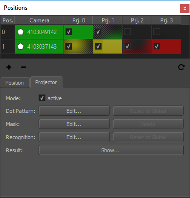
Positions Table
- Cell Color
Quality estimate of measurement result based on comparing the number of detected and the number of projected dots.
- Green
The same amount of dots where detected as where projected.
- Yellow-Red
When less than 100% of the projected points where detected, the color gradually changes from yellow (99% detected) over orange to red (0% detected).
- Red
No points, or more than projected points where detected.
- Cell Fillpattern
Dithered if dot pattern where overridden, solid otherwise.
- Polygon Icon
Shown if a mask is defined.
- Checkmark
A cell is checked, if a projector is activated for calibration on a distinct position.
- Selection
The selection in the positions list updates creators general projector and camera selection. Selecting a position or camera will automatically select all active projectors of this position and the assigned camera. Selecting a projector will select this projector and the camera of related position.
- Tooltip
Shows how many points where detected and how many points where projected.
- Doubleclick Camera or Position
open PosFinder for camera position
- Doubleclick Projector
Open calibration result for projector. (see section Result View)
- Context Menu
Quick access to camera/projector related editors.
- Add Position
add new position with currently selected camera and projectors
- Remove Position
user defines exact position of marker/feature in image. No image analysis is done for this marker
- Update Position List
refresh positions table
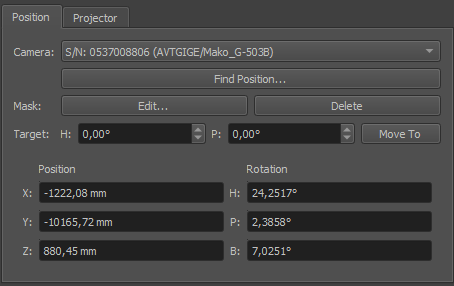
Position Tab
- Camera
Select the camera that should be used on this position.
- Find Position
Find camera position and orientation using Position Finder (see chapter Position Finder).
- Mask Edit
Edit a mask that is applied to the camera image to avoid false point recognitions, e.g. reflective surfaces or flashing projector lenses. It can be combined with projector masks. (see section Mask Editor)
- Mask Delete
Delete mask and use complete camera image for detection.
- Target H/P
Set target heading and pitch for motorized rotation unit.
- Target Move To
Move rotation unit to currently set target rotation.
- Position/Rotation
Camera Position and Orientation on this position.
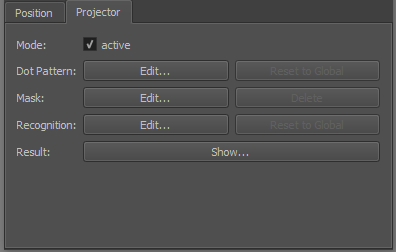
Projector Tab
- Active
Set if selected projector on selected position should be active for calibration.
- Dot Pattern Edit
Override dot pattern for current projector on current position. (see section Dot Pattern Editor)
- Dot Pattern Reset to global
Remove dot pattern override and use global dot pattern settings for current position.
- Mask Edit
Edit a mask that is applied to the camera image to avoid false point recognitions, e.g. reflective surfaces or flashing projector lenses. It can be combined with position mask. (see section Mask Editor)
- Mask Delete
Delete mask and use complete camera image for detection.
- Recognition
Allows to override recognition settings for current projector on current position.
- Recognition Reset to Global:
Removes the override.
- Show Result
Shows a result image where recognized points are marked with a cross and row/column number (see section Result View). If errors in the order are visible or less than 85% of points where recognized the camera parameters, recognition-parameters and masks should be checked and image taking or/and image analysis must be repeated.
