Export Generic Advanced 3D
The Generic Advanced 3D exporter exports data that allows to generate frusti and warping data dynamically during runtime to produce perspectively correct imagery for any viewpoint in a finite volume.
The exported data contains:
3D shape of the projection surface for each projector
Blending information
Black Level Correction information
- Target rectangles as a guide to generate frustum settings for any
eyepoint
Export Settings

- Export Path:
The folder to which all exported files will be exported.
- Shape:
Allows to select between different projection shape formats:
Generic CSV (csv-file)
- Wavefront OBJ (mesh file format that can be read by many 3d
applications)
- Shading:
Allows to adjust image format settings:+
- bmp 24bit (shading encoded in color, should be multiplied with
content to apply)
- bmp 32bit color (shading encoded in color, should be multiplied
with content to apply)
- png 8bit grayscale (shading encoded as gray-values, should be
multiplied with content to apply)
- png 32bit black + alpha (shading encoded in alpha, should be
overlayed above content to apply)
- Black Level Adjust:
Enable to export Black Level Adjust image.
- Target Rectangle:
Allows to adjust the conversion of current frustum settings into target Rectangles by setting a distance and scale value. The distance is set to mixed by default, which means the target distances per projector from the frustum settings in the project are used. The scale value is usually a bit larger than 1.0 to avoid content cut-off, when moving the eyepoint around in a dynamic viewpoint system.
Export Format
CSV Format
Shape and Target Rectangles can be exported as CSV (Comma Seperated Values), a commonly used exchange format for table based data. Filename extension: *.csv Seperator: ; First Line contains column names. Following lines the data sets. Additional culumns might be appended in future.
Coordinate System
X and y axis on the floor. X-axis pointing to the right, y-axis to the front and z-axis to the top. Rotation order is 1.Heading, 2.Pitch, 3.Bank. Distance measures are in millimeters and rotations are given in degrees.

Texture coordinates are defined as normalized values going from top-left (0,0) to bottom-right(1,1).
Shape
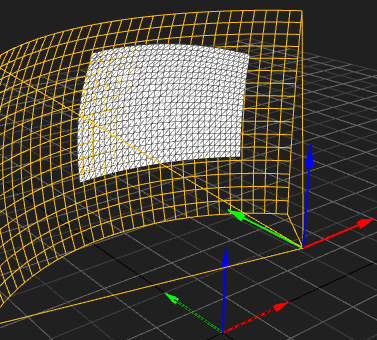
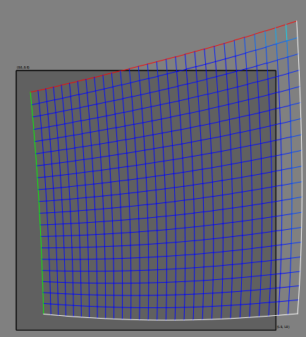
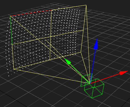
The shape describes where each projector image is shown in 3d space on the physical screen. It furthermore describes which pixel of the projected image is shown where on the physical screen. Two alternative export variants are supported. See following sections.
Generic CSV
The shape can be exported as CSV (Comma Seperated Values), a commonly used exchange format for table based data.
First Line contains column names. Following lines the data sets.
The file contains a regular grid of vertices. Each vertex has a 3d position, a texture-coordinate and a grid index. Vertices are ordered line-wise from top-left to bottom-right. The grid index (column, row) of the last vertex in file is equal to the number of rows – 1 and the number of columns – 1.
- x, y, z:
position of vertex in 3d space (physical screen)
- u, v:
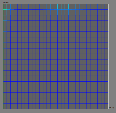
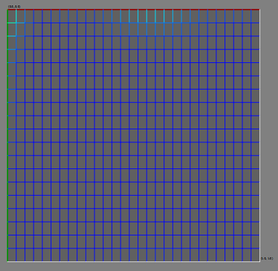
texture coordinate of vertex in normalized texture-space (reference to projector image, top-left is 0,0, bottom-right is 1,1)
- column, row:
column and row index of vertex. The vertex order is ordered and will not be shuffled, the column and row index is more intended for convenience. Number of columns and rows can be extracted from last vertex.
This grid can be used to generate a mesh by spanning triangles/quads between adjacent vertices.
Example:
3D Positions |
UV Koordinates |
|---|---|
|
|
CSV Data:
x;y;z;u;v;column;row
-284.4113;1958.6552;2684.0044;0.0000;0.0000;0;0
-213.1139;1961.8509;2688.3775;0.0345;0.0000;1;0
-140.8579;1963.9186;2691.7009;0.0690;0.0000;2;0
...
1641.2280;1735.1887;1067.2657;0.9310;1.0000;27;19
1697.7215;1700.2307;1067.1855;0.9655;1.0000;28;19
1752.4338;1664.9009;1067.1924;1.0000;1.0000;29;1
The warping mesh for a given camera setting is generated by using the defined uv-koordinates as vertex positions and projecting the 3d shape into virtual camera to calculate the current uv-koordinates.
Viszalization |
Vertex Positions |
UV Koordinates |
|---|---|---|
|
|
|
Wavefront OBJ
The shape can be exported as a triangulated mesh in obj file format as well.
Blending
The blending is exported as an image file. The image has the resolution of the projector and is fitting the already warped projector, no more warping needs to be applied to it.
The file format can be chosen between bmp 24bit, png 32bit color, png 8bit grayscale, png 32bit blacklevel + alpha and xmp 24bit.
Projector (warped) as example |
Color |
Alpha |
|---|---|---|
bmp 24bit |
|
|
png 32bit color |
|
|
png 8bit grayscale |
|
|
png 32bit black + alpha |
|
|
xpm 24bit |
|
Black Level Adjust
The exported black level adjust image is already warped. The image should be added to the content in a linear color-space to be applied.
\(result = \Big(color^{gamma} * (1 - black^{gamma}) + black^{gamma}\Big)^{\frac{1}{gamma}}\)
including blending:
\(result = \Big( (color*blending)^{gamma} * (1 - black^{gamma}) + black^{gamma} \Big)^{\frac{1}{gamma}}\)

Target Rectangle
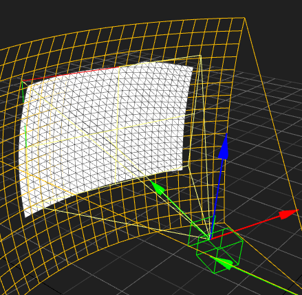
A rectangle placed in 3d space. Usually fitting as close as possible the shape of the corresponding projector shape. It is meant to be used as a target to generate virtual camera settings for given eye-points.
The camera settings can be generated by:
Placing the camera at a given eye-point
- Orienting the camera the same as the target rectangle. Use same
heading/pitch/bank or face camera along target rectangle’s normal and use rectangles up vector for calculating the cameras roll.
- Adjusting Frustum left/right/top/bottom to match target rectangles
left/right/top/bottom border
The target rectangle is exported as an csv file. It contains some redundant values for convenience and supporting alternative ways to calculate new virtual camera settings.
Description of Values:
- x, y, z:
center position in millimeter (x, y ground-plane; z vertical)
- heading, pitch, bank:
orientation in degrees (heading/yaw/z, pitch/x, bank/roll/y)
- left, right, bottom, top:
distance to corresponding rectangle edges in millimeters. Left and bottom typically negative. Left/Right and Top/Bottom usually have same absolute value.
- width, height:
width/height of rectangle in millimeters
- normalx, normaly, normalz:
normal of rectangle facing away from viewer, usually inside screen, so it can be used as viewing vector for camera without inverting
- c0x, c0y, c0z,…. c3x, c3y, c3z:
3d positions of rectangle corners. Clockwise beginning with top-left corner
Example:
Visualization |
Data |
|---|---|
|
x: 406.90 y: 904.86 z: 1747.66
heading: 20.00 pitch: 6.82 bank: 0.00
left: -520.56 right: 520.56
bottom: -363.97 top: 363.97
width: 1041.13 height: 727.9416
normalx: 0.3396 normaly: 0.9330 normalz: 0.1188
c0x: -97.05 c0y: 1042.29 c0z: 2109.05
c1x: 881.29 c1y: 686.20 c1z: 2109.05
c2x: 910.85 c2y: 767.43 c2z: 1386.26
c3x: -67.48 c3y: 1123.52 c3z: 1386.26
|
