Export Generic
The Generic Exporter allows to export to simple and easy to integrate fileformats, and provides many settings to customize your exports.
Export Settings
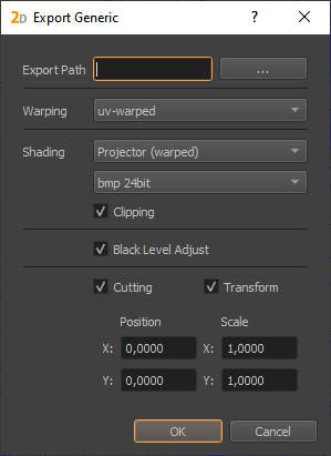
- Export Path:
The folder to which all exported files will be exported.
- Warping:
Allows to select between different warping formats:
none (disabled)
uv-warped (csv-file)
vertex-warped (csv-file)
pixel-warped (warping encoded as pixel color in an image)
See following sections for detailed descriptions about different warping exports.
- Shading:
Allows to adjust image format settings.
First select between different warping styles:
none (disabled)
Projector(warped, no warping needs to be applied)
Cut (warping needs to be applied)
Source (cutting and warping needs to be applied
Second select between different image formats:
bmp 24bit (shading encoded in color, should be multiplied with content to apply)
bmp 32bit color (shading encoded in color, should be multiplied with content to apply)
png 8bit grayscale (shading encoded as gray-values, should be multiplied with content to apply)
png 32bit black + alpha (shading encoded in alpha, should be overlayed above content to apply)
xpm 8bit grayscale (shading encoded as gray-values, should be multiplied with content to apply)
png 16bit grayscale (shading encoded as gray-values, should be multiplied with content to apply) one channel of 16 bit gray values
- Clipping:
Enable to integrate Clipping information in exported blend-files (clipping editor, clipping-image in project-settings)
- Black Level Adjust:
Enable to export Black Level Adjust image. The image should be added to the content in a linear color-space to be applied. As an alternative blendmode, inverse multiply might be a good approximation.
- Cutting:
Enable to export cutting information as csv-files
- Transform:
Enable to adjust the exported cutting range. This can be used to place cutting rectangles in a bigger context. For a non-uniform scale, the cutting rectangles need to be unrotated.
Export Format
Warping, Frustum and Cutting is exported as CSV (Comma Seperated Values), a commonly used exchange format for table based data.
First Line contains column names. Following lines the data sets. Additional culumns might be appended in future.
Blending, Black Level Adjust and Pixel Warping is exported in different image formats.
UV-Warping / Vertex-Warping
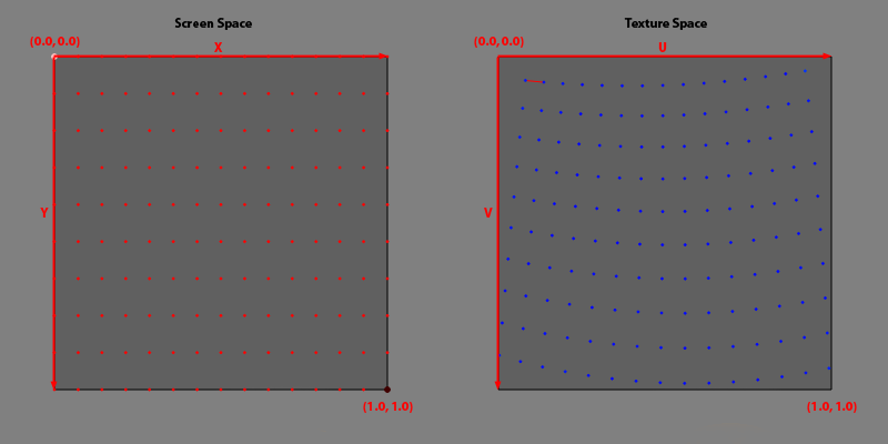
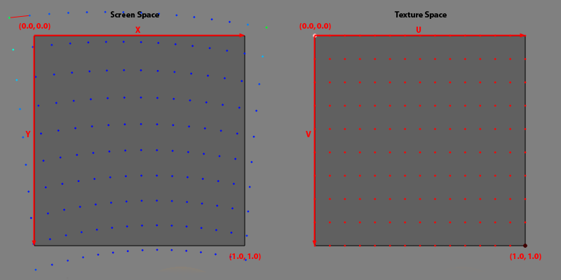
Warping can be exported as a regular grid of vertices. Each vertex has a position, a texture-coordinate and a grid index. Vertices are ordered line-wise from top-left to bottom-right. The grid index (column, row) of the last vertex in file is equal to the number of rows – 1 and the number of columns – 1.
- x, y:
position of vertex in normalized screen-space
- u, v:
texture coordinate of vertex in normalized texture-space
- column, row:
column and row index of vertex. The vertex order is will not be shuffled, the column and row index is more intended for convenience. Number of columns and rows can be extracted from last vertex.
This grid can be used to generate a mesh by spanning triangles/quads between adjacent vertices.This is the prefered usage for software warping. The position – texture-coordinate pairs can also be used to extract a polynomial transformation. Examples:
Visualization |
Data |
|
|---|---|---|
UV-Warping |
|
x;y;u;v;column;row
0.0000;0.0000;0.0813;0.0715;0;0
0.0714;0.0000;0.1366;0.0769;1;0
0.1429;0.0000;0.1936;0.0812;2;0
...
0.8571;1.0000;0.8517;0.9615;12;9
0.9286;1.0000;0.9232;0.9498;13;9
1.0000;1.0000;0.9929;0.9359;14;9
|
Vertex-Warping |
|
x;y;u;v;column;row
-0.1189;-0.0854;0.0000;0.0000;0;0
-0.0222;-0.0958;0.0714;0.0000;1;0
0.0709;-0.1035;0.1429;0.0000;2;0
...
0.8614;1.0410;0.8571;1.0000;12;9
0.9322;1.0533;0.9286;1.0000;13;9
1.0048;1.0679;1.0000;1.0000;14;9
|
Pixel-Warping
Pixel-Warping Encodes warping data in an image. In each pixel, the corresponding uv-coordinate is encoded.
R(8 bit): major u
G(8 bit): minor u
B(8 bit): major v
A(8 bit): minor v
The 16 bit integer representation maps the float range [-0.5, 1.5] to integer values [0, 65535]. That means 0.0 maps to 16384 and 1.0 maps to 49152. Values outside of [-0.5,1.5] are clamped to the neares allowed value. In the following text the float representations are named u and v the corresponding integer representations are named uInt and vInt.
Encoding:
uInt = MAX(MIN(u * 32767 + 16384, 65535), 0);
vInt = MAX(MIN(v * 32767 + 16384, 65535), 0);

r = uInt / 256;
g = uInt % 256;
b = vInt / 256;
a = vInt % 256;
Decoding:
uInt = r * 256 + g;
vInt = b * 256 + a;
u = (uInt - 16384) / 32767;
v = (vInt - 16384) / 32767;
Example:

Blending
There are three options to export blending data. It can be exported as Projector (warped), Cut, or Source image.
The result of the Projector (warped) blending is an image with the resolution of the projector that is fitting the already warped projector.
Exporting the blend file as cut format, results in an image with projector resolution but in this case the image still needs to be warped.
The source export shows the full content space. Cutting and warping still has to be applied to this export.
Apart from these types of blending, the file format can also be chosen, bmp 24bit, png 32bit color, png 8bit grayscale, png 32bit blacklevel + alpha and xmp 24bit.
Projector (warped) as example |
Color |
Alpha |
|---|---|---|
bmp 24bit |
|
|
png 32bit color |
|
|
png 8bit grayscale |
|
|
png 32bit black + alpha |
|
|
xpm 24bit |
|
|
png 16bit |
|
Black Level Adjust
The exported black level adjust image is already warped. The image should be added to the content in a linear color-space to be applied.
\(result = \Big(color^{gamma} * (1 - black^{gamma}) + black^{gamma}\Big)^{\frac{1}{gamma}}\)
including blending:
\(result = \Big( color^{gamma} * blending^{gamma} * (1 - black^{gamma}) + black^{gamma} \Big)^{\frac{1}{gamma}}\)

Frustum (3d)
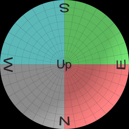
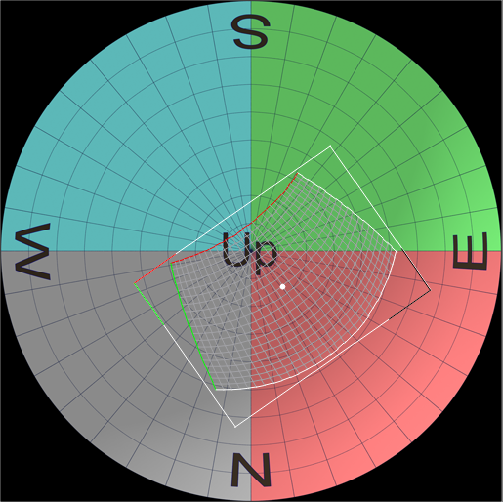
Informations about virtual camera that should be used for one projector.
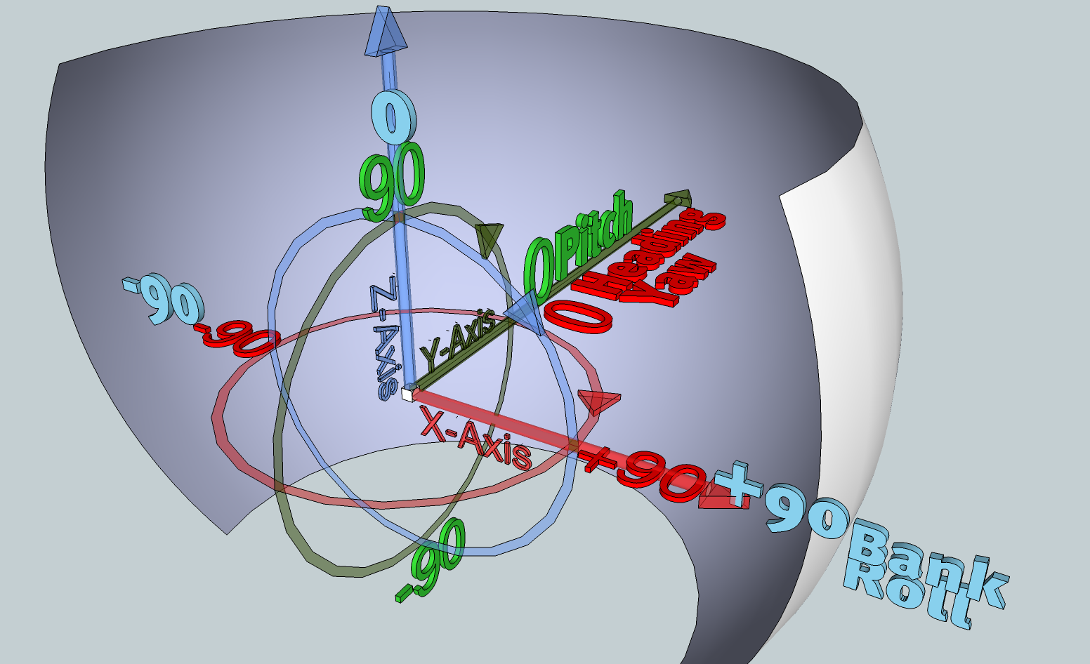
- x, y, z:
position in millimeter (x right, y front; z up)
- heading, pitch, bank:
orientation in degrees (heading/yaw/z clockwise around vertical axis, pitch/x clockwise around right axis, bank/roll/y clockwise around front axis)
- left, right, bottom, top:
opening angles in degrees. Left and bottom typically negative, except for extremely shifted frusti.
- tanLeft, tanRight, tanBottom, tanTop:
tangenz values of frustum borders for convenience
- width:
width of frustum at distance 1.0 (tanRight – tanLeft)
- height:
height of frustum at distance 1.0 (tanTop – tanBottom)
Example:
x;y;z;heading;pitch;bank;left;right;bottom;top;tanLeft;tanRight;tanBottom;tanTop;width;height
0.0000000;0.0000000;0.0000000;-15.00;0.00;0.00;-20.0000000;20.0000000;-20.0000000;20.0000000;-0.3639702;0.3639702;-0.3639702;0.3639702;0.7279405;0.7279405
Cutting (2d)
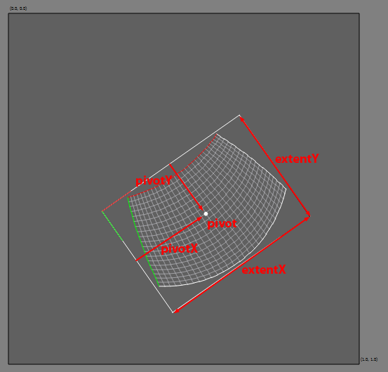
TheCutting rectangle is defined in normalized texture-space. The Top left corner of texture-space is (0,0), the bottom right corner is (1,1).
- posX, posY:
position of the rectangle
- rotation:
rotation of rectangle in degrees clock-wise
- extentX, extentY:
rectangles extent (width, height)
- pivotX, pivotY:
absolut pivot/anchor/rotation-center of rectangle in local coordinates ( The Top left corner is (0,0), the bottom right corner is (extentX, extentY))
- c0x … c3y:
rectangle corner positions, clockwise, beginning with top-left corner of rectangle.
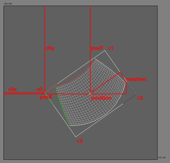
Example: From *.csv file:
posX;posY;rotation;extentX;extentY;pivotX,pivotY;c0x;c0y;c1x;c1y;c2x;c2y;c3x;c3y
0.5629;0.5713;-35.0000;0.4780;0.3503;0.2390;0.1752;0.2667;0.5649;0.6582;0.2907;0.8591;0.5777;0.4676;0.8519;0.2667;0.5649
Reformatted for human readabillity:
posX: 0.5629
posY: 0.5713
rotation: -35.0
extentX: 0.478
extentY: 0.3503
pivotX: 0.239
pivotY: 0.1752
c0x: 0.2667
c0y: 0.5649
