Export Ventuz
The Ventuz exporter exports geometry files (ShapingData_*.dea),
blending files and a text file that includes all the frustum settings
of the virtual cameras.
Configuring the Desktop
In order to have a multi projector setting for a Ventuz presentation the windows desktop has to be set to a span view including all displays that want to be used.
Workflow
First step is to make the usual measurements with the Creator. After generating the 3d Geometry the Creator can be closed, the Mapper3D opened and the project loaded.
In the Mapper 3D virtual cameras will be placed for all displays. All Cameras should have the same position only the rotation angles and frustum setting shall differ between the virtual cameras.
When the setup is satisfying the export itself has to be set up; . Here the export path has to be defined as well as what should be exported. Warping, Frustum values and general shading is essential, Black level adjust (BLA) is not yet supported by Ventuz.
General information for importing into Ventuz
The warping will not be done within the original Ventuz scene but an
additional production layout scene. Two templates for a three
projector setup can be found within the Mapper3d template folder.
Depending whether or not decimal expansion use a comma or a dot the
Ventuz3_Template-ger.vza (for comma) or
Ventuz3_Template-eng.vza (for dot) archive is chosen.
After importing the archive into the project certain things have to be modified and set.
Setting a new Render layout Scene
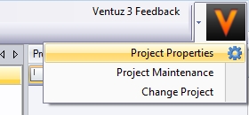
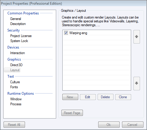
After Importing the provided template it should be set to be the default render layout to ensure that our production will be rendered with the generated warping. The settings for render layouts can be found in the project properties on the right to of the Ventuz window.
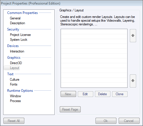
Here, different layouts can be set or modified within the Graphics subsection. By clicking on new, a new layout can be generated, by double clicking on an existing one layout settings can be modified.
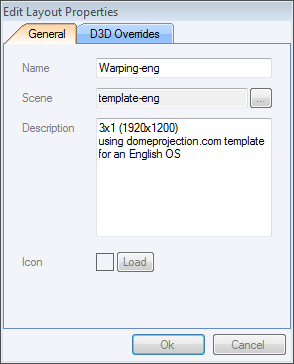
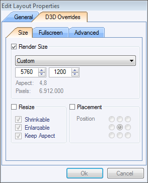
After creating a new Layout it can be given a name and a scene has to be chosen for the new render scene. Afterwards the render size must be set to fit the real desktop setting. In this example, 3 projectors are used with a resolution of 1920x1200 and they are all horizontally aligned therefor the resolution of the render scene has to be 5760x1200.
The Next step is to define this new render scene as default render scene, by checking the check box in front of the scene) which means that every project that will be exported as a presentation will be mapped onto this render scene.
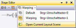
In order to see the result of the warping the output scene has to be active and the stage editor window has to be activated (View -> Stage Editor). Per default it should show up on the left side. Here the render scene can be chosen.
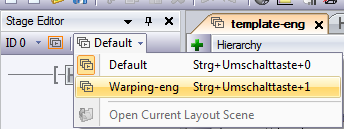
If the layout scene has to be to reedited, choose “open current Layout Scene” a new tab will open showing the layout Scene.
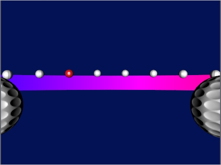
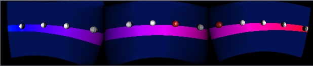
In the render window the view of the scene should be changed now from a plain one to a longer split one
Changing the render layout
In case the projectors are not horizontally aligned or there are more or less than 3 projectors in the project the template can easily be modified. For different layouts just change the viewport positions and sizes but be aware that this setup should always represent the real setup of the windows desktop.
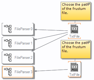
If there are more than 3 Projectors just copy the whole sub-tree starting with the viewport.
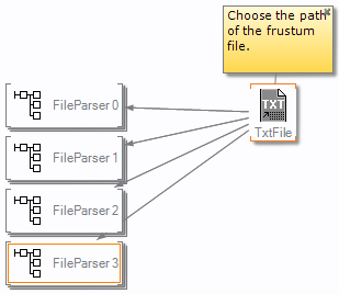
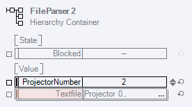
Be aware that nodes will be copied that have a connection to a node of copied group. In this case a text file node that become visible when clicking on the file parser. It is important to delete this copied TxtFile node and create a link from the added file parser to the original TxtFile node. Otherwise it is possible that the wrong data will be displayed.
Importing warping files and setting the virtual camera
If not already open, open the render layout scene (Stage Editor window) by first choosing the layout that has to be changed as being the active layout and than clicking on “Open Current Layout Scene”
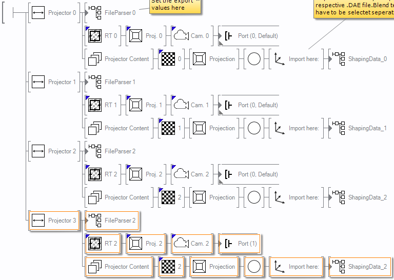
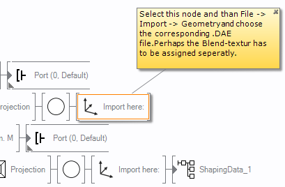
The following picture shows the scene hierarchy with 3 view-ports (one for each projector). The view-ports are set to be all horizontally aligned and the nodes that are attached to them will define the warping and camera setup.
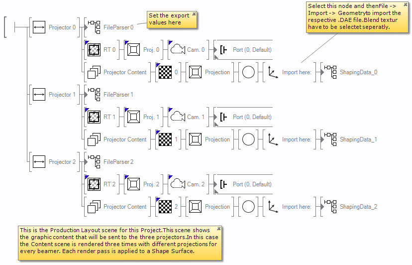
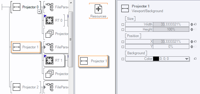
In order to import the warping correctly, following values have to be
changed to set the proper field of view. The first thing to do is to
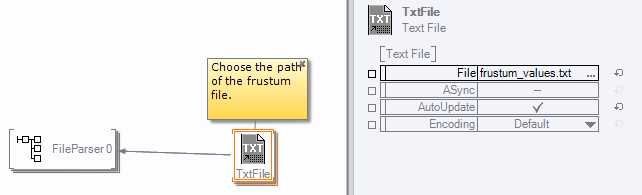
import the frustum_value.txt file. To do so any of the fileParser
nodes has to be selected to bring up the TxtFile node within the
content window. There the text file can be chosen.
It has also to be checked if each FileParser was the right projector number assigned to.
After selecting the frustum_value text file and setting the
projector numbers the warping can be imported. First the old shaping
data has to be deleted, than the shapingData_x.dae file has to be
imported by selecting the “import here:” node an than .
A import dialog will be shown, were nothing has to be changed just click import. Next will be ask were to save the ventuz geometry file, here the old file can be overwritten.
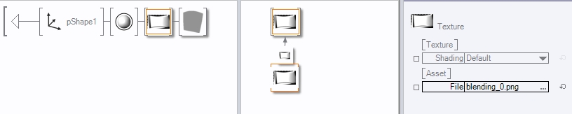
Afterwards the correct blending file has to be set within the
ShapingData_x container (to get into the container double click
on the small arrow in front of the ShapingData node). By default the
blending files that are already in the Images folder will be taken,
change it to the new created one by clicking on the dots in the File
array, a dialog will open with which the new blending file can be
selected.
After Setting all values and importing all data this scene has to be saved in order to use this changed layout for any export.
Please note: an example project (ExampleProject.vpa) which contains
both templates, already set up as render layout, and a demo scene can
also be found within the Mapper2D/Mapper3D templates/ventuz
folder.